Phasor Circuits Analysis: Example Problems and Solutions
Explore examples of phasor circuits analysis with a focus on independent and dependent sources. Learn the convenience of using admittance in impedance calculations and find equivalent impedance in electrical networks. Step-by-step solution provided for determining current and voltage expressions in a time-domain circuit.
Download Presentation

Please find below an Image/Link to download the presentation.
The content on the website is provided AS IS for your information and personal use only. It may not be sold, licensed, or shared on other websites without obtaining consent from the author. If you encounter any issues during the download, it is possible that the publisher has removed the file from their server.
You are allowed to download the files provided on this website for personal or commercial use, subject to the condition that they are used lawfully. All files are the property of their respective owners.
The content on the website is provided AS IS for your information and personal use only. It may not be sold, licensed, or shared on other websites without obtaining consent from the author.
E N D
Presentation Transcript
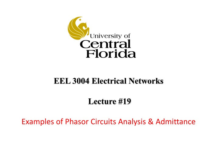
EEL 3004 Electrical Networks Lecture #19 Examples of Phasor Circuits Analysis & Admittance
Lecture Objectives The lecture today will focus on: Example phasor circuits: independent and dependent sources The convenience of using admittance in impedance calculations. Finding the Equivalent Impedance
Example Determine the expressions ix(t) and vx(t) in the following time-domain circuit, given: Variable values Unit Vm1 1 1 Vm2 2 2 R1 R2 L1 L2 C1 C2 10 V 3000 rad/s /3 rad 10 V 2000 rad/s /3 rad 5 18 0.2 mH 0.2 mH 0.8 mF 0.8 mF
Solution: 1) First we transform the time-domain circuit into the phasor-domain, 2) Second solve for phasor currents and voltages as complex numbers by using any analysis method 3) Transform the phasor domain values to time domain.
Since we have two different sources, we apply superposition, First we kill the second source and apply source transformation to the first source,
Combine capacitive and inductive impedances in series with Vs1 to Z1, and transform to current source,
Where, Next, we simplify the circuit further yields Where,
Applying a current to voltage source transformation yields Where, Where,
Now we calculate Vx1, Transforming back the voltage Vx1,
Now we calculate Ix1, Transforming back the current Ix1,
Next we kill the first source and apply source transformation to the second source,
Use source transformation: Where, And,
Simplifying the circuit further By applying a current to voltage source transformation yields Where, Where,
Now we calculate Vx2, Transforming back the voltage Vx2 into time domain
Now we calculate Ix2, Transforming back the voltage Ix2 into time domain
Using the concept of superposition, we calculate vx(t) and ix(t),
Example Given the RC circuit with the dependent source, the current input is given by, Im Determine the expression for vC(t) and iR(t) by using phasor method. Variable Default Unit Im 6 A 3000 rad/s /3 rad R 18 C 0.8 mF g 4
1) First we transform the time-domain circuit into the phasor-domain, Phasor-domain circuit time-domain circuit 2) Second solve for phasor currents and voltages as complex numbers by using any analysis method 3) Transform the phasor domain values to time domain.
Applying KCL at the upper node yields, It can be seen that Vx = VC, Now applying KVL around the loop including the resistor and capacitor yields,
Solving these two equations for IR, Transforming the current IR back to the time-domain yields,
Solving these two equations for VC, Transforming the voltage VC back to the time-domain yields,
Example: For the time-domain circuit given in Fig. 8.18 (a) the voltage source, ??(?) is given by ??? = ??cos?? a) Determine the total impedance in phase-domain seen by the source b) Find the expression for the total current ??? drawn by the source c) Find the expression for the capacitor voltage ??2(?). Where ??= 5?,? = 105??? ?,? = 45 ,?1= 10??,?2= 6??,?1= 20?? ??? ?2= 180?? ???
Solution: The first step is to transfer the circuit from time-domain to frequency- domain as shown Combining impedance of single elements connected in series, ??, and connected in parallel, ??.
Where, 1 ?1= ???1+ ? ??1 1 ?2= (?? ?2) /( ? ??2) The total impedance is given by, ??= ?1+ ?2 Then, the total current drawn by the source is obtained from ??=?? ?? Next, we fins the complex numbers for ?1 and ?2
First Calculate ?1: 1 1 ?1= ???1+ ? = ?(??1 ??1) ??1 1 = ?(105.10?10 3 10 5. 20 10 6 1 = ? 103 20 10 1 ?1= j 999.5
Second Calculate ?2: 1 ?2 ?2= (?? ?2) /( ? ??2) ?2?2 1 (???2)( ? ??2) ?2 = = 1 1 ???2 + ( ? ( 1)?2 ??2) ?(??2 ?2 ?2 ??2) ?2 ?2 ?2? ?2 1 ??2) = = = ? = ? 1 1 1 ?2?2?2 ?(??2 ?(??2 ??2) ??2 ??2 6?10 3 180?10 6 0.0333?103 = ? = ? 1 1 105? 6?10 3 6?102 180?10 1 105 ?180?10 6 600 0.056= ?33.33 33.33 = ? 599.94== ?0.06 ?2= ?0.056
(b) First expressing the voltage source as a cosine function, ??? = ??sin(?? + ?) = ??cos(?? + ? 90 ) ??? = 5cos 100000? 45 ? The total current drawn by the source is obtained from ) ??=?? ?? (? 90 |??| ??? = = |??| ??? ?? ??= |??| ???= 5 135? mA Where, ?? ?? 5 ? |??| = = 999.44 = 5 ?? ???= ? 90? ???= 45 90? 90?= 135?
So, the phasor current Ismay be expressed by, ??= |??| ??? mA mA = 5 135? Polar Form in degrees Polar Form in radians = 5 3?/4 mA = 5? ?3?/4 In Euler s Formula mA Rectangular Form = 3.54 ?3.54 Therefore, in time-domain the corresponding source current is given by, ??? = |??cos(?? +??? = 5cos 105? 135? ??
(c) The phasor capacitor voltage is equal to the voltage across ?2, hence ??? is given by ???= ????= ?2 ?? (??2+???) = 19.65 + ?19.65 ?? = 27.8 135 ?? Where, ?2? ?2 = = ?0.056 1 ?2?2?2 ??2= 90 Therefore, in time-domain the corresponding voltage ??2? is given by ??2? = 27.8cos 105? + 135? ??
Admittance Like in time-domain where the reciprocal of resistance R is defined as the conductance G , in phasor domain reciprocal of impedance is also defined and known as admittance. The admittance, Y , is defined as the ratio of phasor current to phasor voltage. In rectangular format, where Z is expressed Z = R + jX, Y , is expressed as, Where G is known as the conductanceand B is the susceptance and both are measured in Siemens (S).
Admittance The use of admittance is clearly seen when we algebraically sum the admittances of a network consisting of parallel connected impedances. Where, And the phasor current flowing through any of these individual impedance Ii is given by,
Example Determine the input impedance and admittance for each of the following circuits: Variable Values Unit 105 rad/s R 1 k H F L 100 C 5
First we transform the circuit into the phasor-domain, For the first circuit, the input impedance is given by, 1 ????= ? + ?(?? ??) = 1000 + ?8 While the input admittance is given by, 1 ????= = ?1+ ??1 ???? Where, ??2?2 ?2?2?2+ (?2?? 1)2= 1.00?10 3 ?1= ??(?2?? 1) ?2?2?2+ (?2?? 1)2= 8.00 10 6 ?1=
For the second circuit, the input impedance is given by, 1 ????= ?//???// ? = ?2+ ?2 ?? = 0.0063 ?2.5 Where, ?2?2? ?2= ?2(1 ?2??)2+?2?2= 0.0063 ???2(1 ?2??) ?2(1 ?2??)2+?2?2 = 2.5 ?2= While the input admittance is given by, ????=1 1 ?+ ?(?? = 0.001 + ?0.4 ??) ?
Check if this equation is valid: 1 ????= ???? ? Recall, we found ????through the long method ????= 0.001 + ?0.4 ? 1 We can find ????directly by using ????, where we got ???? through the long method, 1 ? ????= = ???? 0.0063 ?2.5 1 0? 1 2.5 98.86?= ?.? 98.86? = 2.5 98.86?= = ?.? ???98.86?+ ?0.4???98.86 = 0.001 + ?0.4 ????= 0.001 + ?0.4 as before!
Example Determine the equivalent impedance, seen between the terminals ab , cd , and cb of the circuit shown, Variable Values Unit 1000 rad/s R1 R2 R3 L1 L2 L3 C1 C2 10 k 6 k 8 k 20 mH 20 mH 20 mH F F 180 180
First we transfer the circuit to the phasor domain, Let, The equivalent impedance Zab is equal to,
Where, Such that,
In the same manner, the equivalent impedance Zcd is equal to, Where,
Such that, Therefore,
In the same manner, the equivalent impedance Zcb is equal to, Where,
Such that, Therefore,
Practice Example: Consider the following time-domain circuit: 1) Convert the time-domain circuit to phasor domain circuit. 2) Determine the input admittance,Yin, seen between terminals ab in rectangular and polar form for the network. 3) Determine the input impedance seen between terminals ab in rectangular and polar form for the network. 4) Determine the time-domain current in L. 5) Determine the expression for the power supplied by the voltage source. Variable Values Unit Vm 5 v 1000 rad/s R1 R2 R3 L 700 700 700 25 mH F C 92


