Physics Exam Preparation Guide for Chapters 16, 17, 18
Get ready for your physics exam with this guide covering topics such as resistive wire, capacitors, and series circuits. Check the details for exam time and requirements.

Download Presentation

Please find below an Image/Link to download the presentation.
The content on the website is provided AS IS for your information and personal use only. It may not be sold, licensed, or shared on other websites without obtaining consent from the author. If you encounter any issues during the download, it is possible that the publisher has removed the file from their server.
You are allowed to download the files provided on this website for personal or commercial use, subject to the condition that they are used lawfully. All files are the property of their respective owners.
The content on the website is provided AS IS for your information and personal use only. It may not be sold, licensed, or shared on other websites without obtaining consent from the author.
E N D
Presentation Transcript
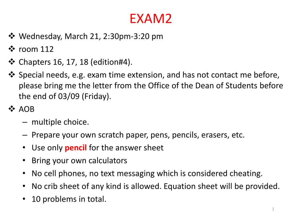
EXAM2 Wednesday, March 21, 2:30pm-3:20 pm room 112 Chapters 16, 17, 18 (edition#4). Special needs, e.g. exam time extension, and has not contact me before, please bring me the letter from the Office of the Dean of Students before the end of 03/09 (Friday). AOB multiple choice. Prepare your own scratch paper, pens, pencils, erasers, etc. Use only pencil for the answer sheet Bring your own calculators No cell phones, no text messaging which is considered cheating. No crib sheet of any kind is allowed. Equation sheet will be provided. 10 problems in total. 1
Twice the Length Nichrome wire (resistive) Quantitative measurement of current with a compass D V = = i nAuE nAu L Current is halved when increasing the length of the wire by a factor of 2. 2
Doubling the Cross-Sectional Area If A doubles, the current doubles. Nichrome wire 3
Two Batteries in Series Why light bulb is brighter with two batteries? Two batteries in series can drive more current: Potential difference across two batteries in series is 2emf doubles electric field everywhere in the circuit doubles drift speed doubles current. - EL = 2 0 emf -EL emf = 0 emf 2 emf Work per second: = E E = L L = = / / P = W T qEL T ieEL = i = nAu2emf emf = = i nAuE nAu ( / ) q T EL L L 2 2emf L 2 P2batt= eLnAu emf L P1batt= eLnAu P = nAueLE2 P2batt= 4 P1batt 4
Capacitance -Q +Q / Q A Electric field in a capacitor: E = 0 f i V = = Es V E l d E 0 / Q A A = = V s Q V s 0 ~ Q V In general: s Definition of capacitance: V C Q = Capacitance of a parallel- plate capacitor: Wiki: The SI unit of capacitance is the farad (symbol: F), named after the English physicist Michael Faraday 0 A = C Capacitance s 5
Capacitor: Charging and Discharging Charging Discharging Will the bulb light up during the charging and discharging process? A. neither B. Yes for both C. Yes for charging process only D. Yes for discharging process only. What happens when the plate is infinitely large? 6
Capacitor: Discharge Electron Current Electric Field 7
Capacitor: Charging Fringe field of a capacitor rises until E=0 in a wire static equilibrium. 8
The Effect of Different Light Bulbs Thin filament Thick filament Which light bulb will glow longer? Which one is initially brighter? 1) Round is initially brighter capacitor gets charged more? 2) Long bulb glows longer capacitor gets charged more? After current stops, Voltage across capacitor = Voltage across battery no matter which bulb is used. Capacitor charged by same amount in both cases. 9
IClicker Question: Effect of the Capacitor Disk Size Use two different capacitors in the same circuit Same amount of charge on both capacitors 1. In the first moment of discharging, which capacitor will make the bulb glow brighter? 2. Which capacitor will make the light bulb glow longer? A. Upper longer, lower brighter B. Upper longer, upper brighter C. Lower longer, lower brighter D. Lower longer, upper brighter / Q 2 A s Fringe field: E 1 R 0 10
iClicker question: Effect of the Capacitor Disk Separation Same amount of charge on both capacitors 1. In the first moment of discharging, which capacitor will make the bulb glow brighter? 2. Which capacitor will make the light bulb glow longer? A. Upper longer, lower brighter B. Upper longer, upper brighter C. Lower longer, lower brighter D. Lower longer, similar brightness / Q 2 A s Fringe field: E 1 R 0 11
Effect of Insulator in Capacitor Same amount of charge on both capacitors Insulator In the first moment of discharging , which capacitor will cause the bulb to produce more light? Which capacitor will make the light bulb glow longer? A. Upper longer, lower brighter B. Upper longer, upper brighter C. Lower longer, lower brighter D. Lower longer, upper brighter Fringe field: / Q 2 A s E E 1 dipoles R 0 12
Parallel Capacitors Initial moment: brighter? Will it glow longer? / Q 2 A s Fringe field: E 1 R 0 Capacitors in parallel effectively increase A 13
An Isolated Light Bulb Will it glow at all? How do electrons flow through the bulb? A. Yes B. No because it s an open circuit. 14
The Current Node Rule in a Capacitor Circuit Charge conservation: i in steady state Ii > 0 for incoming Ii < 0 for outgoing = 0 iI I1 = I2+ I3 Capacitor transients: not a steady state! Cannot use Kirchhoff rule for a part of a capacitor (area 1 or 2) But can use for capacitor as a whole (area 3) 15
Conductivity with two kinds of charge carrier = + q n u q n u 1 1 1 2 2 2 17
Series Resistance Vbatt + V1 + V2 + V3 = 0 emf - R1I - R2I -R3I = 0 emf = R1I + R2I +R3I emf = (R1 + R2 +R3) I emf = RequivalentI , where Requivalent= R1 + R2 +R3 For resistors made of the same material and with the same A it follows straight from the definition of resistance: L R = + + = Lequivalent L L L 1 2 3 A 20
Parallel Resistance I = I1 + I2 + I3 emf emf emf = + + I R R R 1 2 3 emf = 1 R1 +1 +1 emf I = R2 R3 Requivalent 1 1 R 1 R 1 R = + + Requivalent 1 2 3 For resistors made of the same material and with the same A it follows straight from the definition resistance: L R L R 1 A = + + = = Aequivalent A A A 1 2 3 A 21
Kirchhoffs Rules Kirchhoff s Rule 2: Loop Rule When any closed loop is traversed completely in a circuit, the algebraic sum of the changes in potential is equal to zero. = 0 V Coulomb force is conservative i loop Kirchhoff s Rule 1: Junction Rule The sum of currents entering any junction in a circuit is equal to the sum of currents leaving that junction. = I I i j in out Conservation of charge In and Out branches Assign Ii to each branch 22
Circuit Analysis Tips Simplify using equivalent resistors Label currents with arbitary directions If the calculated current is negative, the real direction is opposite to the one defined by you. Apply Junction Rule to all the labeled currents. Useful when having multiple loops in a circuit. Choose independent loops and define loop direction Imagine your following the loop and it s direction to walk around the circuit. Use Loop Rule for each single loop If current I direction across a resistor R is the same as the loop direction, potential drop across R is V = I R, otherwise, V = I R For a device, e.g. battery or capacitor, rely on the direction of the electric field in the device and the loop direction to determine the Potential drop across the device 23 Solve simultaneous linear equations
Loop Example with Two EMF Devices = 0 V i loop + = 0 IR IR Ir IR Ir 1 2 2 2 3 1 1 = I 1 + 2 + + + R R R r r 1 2 3 1 2 If 1 < 2, we have I<0 !? This just means the actual current flows reverse to the assumed direction. No problem! 24
Finding Potential and Power in a Circuit ( ) V 0 12 = + 1 V I a But what is I? Must solve for I first! = + + + = 12 4 = 0.5 ( ) 0 I A + 1 5 5 1 4 0.5 1 11.5( ) = 12 V V a = = 5 9( ) V V V I b a supplied by 12V battery = 12 0.5 = 6( ) P W 12 V dissipated by resistors 2( ) W = = 2 0.5 16 4( ) R P W The rest? Just means 0 V here into 4V battery (charging) 4 0.5 = = P 4 V 25
iClicker question: Series Resistance emf = 1.5v, R1 = R2 = R3 =5 ohm, what is the currents inside the circuit? A. 0.3 A B. 1.5 A C. 0.1A D. 0.15A E. 1.0A 26
iClicker question: Parallel Resistance emf = 1.5v, R1 = R2 = R3 =5 ohm, what is the currents going through R1? A. 0.3 A B. 1.5 A C. 0.1A D. 0.9A E. 1.0A 27
Charging a Battery Positive terminal to positive terminal Charging EMF > EMF of charged device Say, R+r1+r2=0.05 (R is for jumper cables). Then, 12 11( ) 0.05 ( ) 11 20 P power into battery 2 good battery (12V) V = = 20( ) I A battery being charged (11V) = = 220( ) W 2 If connected backward, 12 11 I = + = 46 ( 0 ) A 0.0 5 Large amount of gas produced Huge power dissipation in wires 28
Using Kirchhoffs Laws in Multiple Loop Circuits = + i i i Identify nodes and use Junction Rule: 3 1 2 Identify independent loops and use Loop Rule: i R i R i R + + ( ) 2 1 2 1 2 2 i i R i R + ( ) 2 1 2 1 1 1 i i R i R + Only two are independent. = 0 i 1 1 1 2 2 2 1 1 ( i R ) ( + = 0 ) i R 2 1 2 1 + = 0 i i R 1 1 1 1 2 1 29
iClicker Question I1+I2 I2 What s the current I1 ? I1 (a). 2.0A (b). 1.0A (c). -2.0A (d). -1.0A (e). Need more information to calculate the value. 30
I1+I2 I2 Sketch the diagram Simplify using equivalent resistors Label currents with directions I1 Use Junction Rule in labeling Choose independent loops Use Loop Rule Replace by equivalent R=2 first. Solve simultaneous linear equations + = = 18 12( 3 I + + = = 3 2 3 I I ) 6 6 0 0 I I I I 1 2 1 2 I 1 + 21 2 6 5 21 I I 2 2 1 1 2 = = 3( ), A I 1( ) I A 2 1 31
iClicker Question What is the current through R1 ? 30 30 a. 0.575A R1 R2 45V 45V b. 0.5A R3 30 c. 0.75A d. 0.33A e. 1.5A 32
Real Batteries: Internal Resistance Drift speed of ions in chemical battery: ( NC F v ~ ) eE C In usual circuit elements: E J = In a battery: rint - internal resistance force I F = = ~ J E NC e emf C unit charge A F I F s s = = = , assuming uniform field: E V E s I NC NC C C e A e A Vbattery = emf r I int 33
Ammeters, Voltmeters and Ohmmeters Ammeter: measures current I Voltmeter: measures voltage difference V Ohmmeter: measures resistance R 34
Ammeter Design: rint Ammeter is inserted in series into a circuit measured current flows through it. A A rint emf R Process of measuring requires charges to do some work: Internal resistance emf I = RI = 0 No ammeter: emf R emf + = I = 0 emf int r I RI With ammeter: R int r Internal resistance of an ammeter must be very small 35
Voltmeter Voltmeters measure potential difference VAB add a series resistor to ammeter V = I R Measure I and convert to VAB=IR Connecting Voltmeter: Higher potential must be connected to the + socket and lower one to the - socket to result in positive reading. 36
Voltmeter: Internal Resistance VAB in absence of a voltmeter R1 R + VAB = 2 emf R R B emf 1 2 rint VAB in presence of a voltmeter R VAB 1 + R2 A || 2 int = emf R R int || 2 A R int r + = 2 R int || 2 R int r 2 Internal resistance of a voltmeter must be very large 37
Ohmmeter How would you measure R? emf I = R A emf = R I Ohmmeter Ammeter with a small voltage source 38
Quantitative Analysis of an RC Circuit = = 0 round V emf RI V _ trip C Q VC= Q = C 0 emf RI C =emf Q /C I =dQ dt R emf I = 0 Initial situation: Q=0 R d Q and I are changing in time dt 1 1 dI dQ dI dI d emf d Q = = = I dt RC dt dt RC dt dt R dt RC 39
RC Circuit: Current 1 dI = I dt 1 RC 1 = dI dt I RC I t 1 1 I 0 = dI dt Current in an RC circuit I RC 0 = / t RC I I e 0 t = ln ln I I 0 RC I t What is I0 ? = ln I RC 0 Current in an RC circuit t I emf = e = / t RC RC I e I R 0 40
RC Circuit: Charge and Voltage What about charge Q? dQ I = dt dQ = Idt Current in an RC circuit t t emf = / t RC 0 0 I I e = = / t RC Q Idt e dt 0 R ( ) 1 e t/RC Current in an RC circuit Q = C emf emf = / t RC I e Q R V = C Check: t=0, Q=0, t--> inf, Q=C*emf 41
RC Circuit: Summary Current in an RC circuit emf = / t RC I e R Charge in an RC circuit ( ) 1 e t/RC Q = C emf Voltage in an RC circuit V = emf ( ) 1 e t/RC 42
The RC Time Constant Current in an RC circuit emf = / t RC I e R When time t = RC, the current I drops by a factor of e. RCis the time constant of an RC circuit. 1 = = = / 1 t RC . 0 37 e e . 2 718 A rough measurement of how long it takes to reach final equilibrium 43


/(V/m)")