Explore pipe flow problems related to nodal head, discharge, and diameter determination, along with detailed solutions and equations for turbulent and laminar flow scenarios. Example calculations provided for practical understanding.
Please find below an Image/Link to download the presentation.
The content on the website is provided AS IS for your information and personal use only. It may not be sold, licensed, or shared on other websites without obtaining consent from the author. If you encounter any issues during the download, it is possible that the publisher has removed the file from their server.
You are allowed to download the files provided on this website for personal or commercial use, subject to the condition that they are used lawfully. All files are the property of their respective owners.
The content on the website is provided AS IS for your information and personal use only. It may not be sold, licensed, or shared on other websites without obtaining consent from the author.
E N D
Presentation Transcript
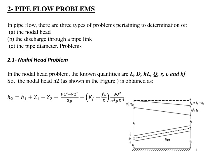
2- PIPE FLOW PROBLEMS In pipe flow, there are three types of problems pertaining to determination of: (a) the nodal head (b) the discharge through a pipe link (c) the pipe diameter. Problems 2.1- Nodal Head Problem In the nodal head problem, the known quantities are L, D, hL, Q, , and kf. So, the nodal head h2 (as shown in the Figure ) is obtained as: ?12 ?22 2? 8?2 ?2?? 4 ??+?? 2= 1+ ?1 ?2+ ? 1
2.2- Discharge Problem For a long pipeline, form losses can be neglected. Thus, in this case the known quantities are L, D, hf, , and . Swamee and Jain (1976) gave the following solution for turbulent flow through such a pipeline: 1.78 ? = 0.965 ?2 ?? ?/? ?? 3.7 ?+ ? ?? ?/? For laminar flow, the Hagen Poiseuille equation gives the discharge as: ? = ??4 ? 128 ? Swamee and Swamee (2008) gave the following equation for pipe discharge that is valid under laminar, transition, and turbulent flow conditions: 0.25 4 4 8 128 415 1.775 ? = ?2?? ?/? + 1.153 ?? 3.7 ?+ ? ?? ?/? ? ?? ?/? ? ?? ?/? 2
2.3- Diameter Problem Diameter Problem In this problem, the known quantities are L, hf, , Q and . However, for turbulent flow in a long gravity main, Swamee and Jain (1976) obtained the following solution for the pipe diameter: 5.20.04 4.75 L L Q Q 2 ? ? ? ? = 0.66 1.25 + Q Q 9.4 ? ? For laminar flow, the Hagen Poiseuille equation gives the diameter as: 0.25 128 ? ? ? ? ? = Swamee and Swamee (2008) gave the following equation for pipe diameter that is valid under laminar, transition, and turbulent flow conditions: 5.20.04 4.75 6.25 L L Q Q 2 ? ? 214.75 ? ? ? + + 1.25 + Q Q 9.4 ? = 0.66 ? ? ? ? 3
Example 3 As shown in figure, a discharge of 0.1 m3/s flows through a CI pipe main of 1000 m in length having a pipe diameter 0.3 m. A sluice valve of 0.3 m. (Kf = 0.15) size is placed close to point B. The elevations of points A and B are 10 m. and 5 m. respectively. Assume water temperature at 20o c. Calculate the following: 1. Terminal pressure h2 at point B and head loss in the pipe if the terminal pressure h1 at point A is 25 m. 2. The discharge in the pipe if the head loss is 10 m. 3. The CI gravity main diameter if the head loss in the pipe is 10 m. and a discharge of 0.1 m3/sflows in the pipe. 4
2- If the total head loss in the pipe is predefined equal to 10 m, the discharge in CI pipe of size 0.3 m can be calculated using this Equation for a turbulent flow: 1.78 ? = 0.965 ?2 ?? ?/? ?? 3.7 ?+ ? ?? ?/? 1.78 1.012 10 6 0.00025 3.7 0.3+ ? = 0.965 0.32 9.81 0.3 10/1000 ?? 0.3 9.81 0.3 10/1000 ? = 0.123 ?3/? 3- the gravity main diameter for preselected head loss of 10 m and known pipe discharge 0.1 m3/s for a turbulent flow is: 5.20.04 4.75 L L Q Q 2 ? ? ? ? = 0.66 1.25 + Q Q 9.4 ? ? 5.20.04 4.75 1000 1000 ?.? 2 9.81 10 ? = 0.284 ? 1000 9.81 10 ? = 0.66 0.000251.25 + 1.012 10 6 ?.? 9.4 6
3- Equivalent Pipe In the water supply networks, the pipe link between two nodes may consist of a single uniform pipe size or a combination of pipes in series or in parallel. The set of pipes arranged in parallel and series can be replaced with a single pipe having the same head loss across points A and B and also the same total discharge Q. Such a pipe is defined as an equivalent pipe. 3-1 : Pipes in Series ?= ?1+ ?2+ ?3+ Q = ?1= ?2= ?3= ?= ?=1 If ??= ?????????? ???? Then ?= 8????2 ?2???5= 8????2 ?2???5 ; ? 8??2 ?2???5 ?=1 ? ?? 8??2 ?2???5 ?=1 ? ? ?=1 ?? ?.? ? ?=? ?=? ?? ?? ??? ??= ? 7
Example 4 An arrangement of three pipes in series between tank A and B as shown below. Calculate the equivalent pipe diameter and the corresponding flow. Assume f=0.02 and neglect minor losses. 0.2 0.2= 0.185 m ? ?=1 ?=1 8???2 ?2??5 = 20 = 8 0.02 1500 ?2 ?? ?? ??5 500+600+400 500 0.25+600 = ??= 0.45+400 ? 0.155 ? = 0.042 ?3/? ?= ?2 9.81 0.1855 8
3-2 Pipes in Parallel ?= ?1= ?2= ?3= ? = ?1+ ?2+ ?3+ ??= ???2??? ? 8??? For N pipes in parallel 0.5 (1) 0.5 ??? ? 8??? ? ??2 ? = ? ?=1 . 2 The discharge Q flowing in equivalent pipe is 0.5 ??? ? 8??? ? = ???2 Equating Eqs. (2) and (3) result (3) 0.4 0.5 ?? ?? ??2.5 ??= 9