Pipe Flow Simulation and Analysis - Mechanics of Fluids and Transport Processes Lab
Conduct a simulation of laminar pipe flow to analyze axial velocity profiles, centerline velocity, pressure distribution, and wall shear stress using Computational Fluid Dynamics (CFD) tools like ANSYS. Explore the differences between laminar and turbulent flow, Reynolds number implications, and visualization techniques for flow patterns. Design your simulation step by step with ANSYS Workbench, ANSYS Design Modeler, Mesh, and Fluent for complete physics setup and result analysis.

Download Presentation

Please find below an Image/Link to download the presentation.
The content on the website is provided AS IS for your information and personal use only. It may not be sold, licensed, or shared on other websites without obtaining consent from the author.If you encounter any issues during the download, it is possible that the publisher has removed the file from their server.
You are allowed to download the files provided on this website for personal or commercial use, subject to the condition that they are used lawfully. All files are the property of their respective owners.
The content on the website is provided AS IS for your information and personal use only. It may not be sold, licensed, or shared on other websites without obtaining consent from the author.
E N D
Presentation Transcript
1. Overview of Pipe Flow 2. CFD Process 3. ANSYS Workbench 4. ANSYS Design Modeler (Geometry) 5. ANSYS Mesh 6. ANSYS Fluent 6.1. Physics (Setup) 6.2. Solution 6.3. Results 2/19/2025 2 ENGR:2510 Mechanics of Fluids and Transport Processes 2016F
Simulation of laminar pipe flow will be conducted for this lab Axial velocity profile, centerline velocity, centerline pressure, and wall shear stress will be analyzed Computational fluid dynamics (CFD) results for the friction factor and the velocity profile will be compared to analytical fluid dynamics (AFD) This lab will cover concept of laminar vs. turbulent flow and developing length for pipe flows Flow visualization between two parallel plates (starts at 14:25) 2/19/2025 3 ENGR:2510 Mechanics of Fluids and Transport Processes 2016F
Flow in pipe with Reynolds number (Re) ?? =?? where U is an inflow velocity, D is a diameter of pipe, ? is a kinematic viscosity Laminar : Re < 2300 Turbulent : Re > 2300 ?=???????? ?????? ??????? ?????? Differences between laminar and turbulent flow (mean) Velocity profile Pressure drop Developing length Wall shear stress and friction factor Note: Refer to Chapter 8 of your book for more details Flow visualization of transition from laminar to turbulent flow 2/19/2025 4 ENGR:2510 Mechanics of Fluids and Transport Processes 2016F
The overall procedure for simulation of pipe flow is shown on chart below Although we will be making the mesh before we define the physics you have to know the physics to design appropriate mesh. Physics Geometry Results Solution Mesh Structure (ANSYS Mesh) Pipe (ANSYS Design Modeler) General (ANSYS Fluent - Setup) Solution Methods (ANSYS Fluent - Solution) Monitors (ANSYS Fluent - Solution) Plots (ANSYS Fluent- Results) Model (ANSYS Fluent - Setup) Uniform (ANSYS Mesh) Graphics and Animations (ANSYS Fluent- Results) Boundary Conditions (ANSYS Fluent -Setup) Laminar Reference Values (ANSYS Fluent - Setup) Solution Initialization (ANSYS Fluent -Solution) 2/19/2025 5 ENGR:2510 Mechanics of Fluids and Transport Processes 2016F
Design your simulation using ANSYS Workbench ANSYS Design Modeler (Geometry) ANSYS Mesh (Mesh) ANSYS Fluent (Physics, Solution and Results) 2/19/2025 6 ENGR:2510 Mechanics of Fluids and Transport Processes 2016F
Symmetric property of the flow is used to create 2D representation of the 3D pipe flow R D L Wall Parameter Radius of pipe, R Diameter of pipe, D Length of pipe, L Value 0.02619 m 0.05238 m 7.62 m Flow Inlet Outlet Center 2/19/2025 7 ENGR:2510 Mechanics of Fluids and Transport Processes 2016F
Create uniform grid distribution (for laminar flow, Pre-lab 1) 2/19/2025 8 ENGR:2510 Mechanics of Fluids and Transport Processes 2016F
Using ANSYS fluent define physics of the flow, solve CFD simulation and analyze results Physics (Setup) Solution Results 2/19/2025 9 ENGR:2510 Mechanics of Fluids and Transport Processes 2016F
Laminar flow Air properties Boundary Conditions (BC) No-slip: velocities and pressure gradient is zero (??= 0,??= 0, Symmetric: radial velocity and gradients of axial velocity and pressure are zero (??? ?? ??= 0) ??= 0, ??= 0, ?? ??= 0) Inlet velocity: uniform constant velocity (??= 0.2 [?/?],??= 0,?? Outlet: (gauge) pressure is imposed to the boundary (??? ??= 0) ??= 0,? =??????= 0 (??? ??????1)) ??= 0, ??? r Wall No slip BC Flow Inlet Velocity inlet BC Outlet Pressure outlet BC x Center Axisymmetric BC Zero slop at center or ??? ??= 0 2/19/2025 10 ENGR:2510 Mechanics of Fluids and Transport Processes 2016F
A limiting behavior in the solution of the equations Represented by the history of residuals or errors made by previous iterative solutions A converged solution is not necessarily an accurate one due to iteration number, domain size, mesh resolution and numerical schemes Continuity, momentum equation have their own residual histories 2/19/2025 11 ENGR:2510 Mechanics of Fluids and Transport Processes 2016F
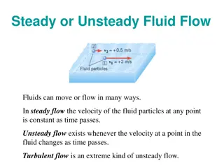
Developed length is distance from entrance to a point where flow is fully developed Fully developed flow does not change velocity profile or velocity gradient in axial direction is zero Pressure drops linearly Axial velocity or skin friction distribution along axis can be used to determine the length Developing region Developed region 2/19/2025 12 ENGR:2510 Mechanics of Fluids and Transport Processes 2016F
Flow can be visualized in detail by using CFD 2/19/2025 13 ENGR:2510 Mechanics of Fluids and Transport Processes 2016F
Bring your EFD 2 Data Reduction Sheet for the CFD Lab 1 by next week Deadline for the CFD Lab 1 report is two weeks after from your CFD lab 1 (not Pre-lab 1) Use the Lab drop-box when turning in your lab reports Come to the office hours for any help 2/19/2025 14 ENGR:2510 Mechanics of Fluids and Transport Processes 2016F


")