Plasma Acceleration at FACET II: Cutting-Edge Research and Discoveries
Dive into the innovative world of FACET II at SLAC National Accelerator Laboratory, where cutting-edge research on plasma wakefield acceleration is pushing the boundaries of high-energy physics. Explore how ultrabright electron bunches with narrow energy spreads are produced, paving the way for future collider technologies and advanced science applications.

Download Presentation

Please find below an Image/Link to download the presentation.
The content on the website is provided AS IS for your information and personal use only. It may not be sold, licensed, or shared on other websites without obtaining consent from the author. If you encounter any issues during the download, it is possible that the publisher has removed the file from their server.
You are allowed to download the files provided on this website for personal or commercial use, subject to the condition that they are used lawfully. All files are the property of their respective owners.
The content on the website is provided AS IS for your information and personal use only. It may not be sold, licensed, or shared on other websites without obtaining consent from the author.
E N D
Presentation Transcript
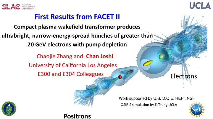
First Results from FACET II Compact plasma wakefield transformer produces ultrabright, narrow-energy-spread bunches of greater than 20 GeV electrons with pump depletion Chaojie Zhang and Chan Joshi University of California Los Angeles E300 and E304 Colleagues Electrons Positrons Work supported by U.S. D.O.E. HEP , NSF OSIRIS simulation by F. Tsung UCLA Positrons
SLAC National Accelerator laboratory Was one of the premier high energy physics lab and premier linear accelerator lab (1960-2010) Since 2010 it has become one of the main centers in the world to do atto- and femto second science using X-ray Free electron laser 1)Our work on Plasma-based acceleration is driven by working Towards a ee+ collider at the energy frontier 2) Expanding the capabilities of the LCSS X-FEL
What and where is FACET II? SLAC Sight in Menlo Park, CA today SLC : First 100 GeV CM e-e+ Linear Collider in the World Glorious history of PWFA Experiments at SLAC 1998 First non-HEP experiment-plasma wakefield accelerator approved 2004 PWFA produces 3.5 GeV energy gain 2006 PWFA doubles the energy of the SLAC s 42 GeV beam 2014 High efficiency acceleration of a distinct second bunch, beam loading 2015 High gradient acceleration of positrons 2009 SLAC s LCLS X_FEL comes on line 2023 LCLS II produces first light
Energy Doubling (10-20+ GeV) with < 1% Energy Spread, Low Emittance preservation, Pump Depletion and > 40% energy transfer Two-bunch PWFA efficiency Plasma and beam density with on-axis Ezline out Beam matching and emittance preservation Beam Energy Energy Doubling Drive Bunch Drive Bunch Trailing Bunch Trailing Bunch SLAC Linac can not provide micron-level transverse emittance bunches, :produce our own Simulations by W. An UCLA, .Joshi et al. PPCF 2018 4
We have characterized and demonstrated use of a~2 m long hydrogen plasma
0.5-degree amplitude and phase fluctuations in RF 100 Beamline simulations of the FACET II Linac and the W compressor shows gross variations of beam current profiles because of amplitude and Phase variation of RF . This did not matter when we used Li vapor to produce plasma Li (IP 6 eV) With hydrogen (IP >13 eV need Ipeak > 30 KA to ionize H atoms) Also the length of the fully ionized plasma produced depends on peak current
(3-stage hydrogen source that enabled plasma formation thru plasma focusing downramp injection, self-matching into a meter scale wake without emittance blowup ) Experimental Set-up Slowly flowing H gas between two Be foils 4.1 m apart with 0.5 mm holes for differential pumping 2 cm long hydrogen gas jet after 1.25 m of lower density (6x 1016 cm-3) gas region Insertable gas jet that produces a variable scale-length downramp, peak density 1-2x1017 cm-3 Downramp followed by a second 2.85m long low density (6x 1016 cm-3) H region
Three Stage (region) plasma source 3D PIC CODE SIMULATIONS OF FIELD IONIZATION OF H SHOWING PLASMA LENSING SHIFT OF THE PLASMA BACKWARD TOWARDS FIRST BE FOIL, Ipeak = `100 kA Ref. C. Zhang et.al., PPCF , 66,025013 (2024) Vaccum Focus ?*=50 cm Vacuum Focus Longitudinal Current profile of the drive Beam, about 1-5% of shots so at 5 Hz,1 data point per 4-20 seconds Blade 1.7 m 0.5 m Region2 Down ramo Region 1 Plasma Lens Region 3 Acceleration of matched beam PUMP Depletion Length
Energy Transfer Efficiency from the Drive Bunch to the Wake 60% ?
Three Stage (region) plasma source at Z=0 Ref. C. Zhang et.al., PPCF , 66,025013 (2024) 3D PIC CODE SIMULATIONS OF FIELD IONIZATION OF H SHOWING PLASMA LENSING SHIFT OF THE PLASMA BACKWARD TOWARDS FIRST BE FOIL, Ipeak = 100 kA Vaccum Focus ?*=50 cm Vacuum Focus Longitudinal Current profile of the drive beam 1.7 m 0.5 m Region2 Down ramo Region 1 Plasma Lens Region 3 Acceleration of matched beam PUMP Depletion Length
Three Stage (region) plasma source at Z = +25 cm Ref. C. Zhang et.al., PPCF , 66,025013 (2024) 3D PIC CODE SIMULATIONS OF FIELD IONIZATION OF H SHOWING PLASMA LENSING SHIFT OF THE PLASMA BACKWARD TOWARDS FIRST BE FOIL, Ipeak = 100 kA Vaccum Focus ?*=50 cm Vacuum Focus Longitudinal Current profile of the drive beam 1.7 m 0.5 m Region2 Down ramo Region 1 Plasma Lens Region 3 Acceleration of matched beam PUMP Depletion Length
Three Stage (region) plasma source at Z = +50 cm Ref. C. Zhang et.al., PPCF , 66,025013 (2024) 3D PIC CODE SIMULATIONS OF FIELD IONIZATION OF H SHOWING PLASMA LENSING SHIFT OF THE PLASMA BACKWARD TOWARDS FIRST BE FOIL, Ipeak = 100 kA Vaccum Focus ?*=50 cm Vacuum Focus Longitudinal Current profile of the drive beam 1.7 m 0.5 m Region2 Down ramo Region 1 Plasma Lens Region 3 Acceleration of matched beam PUMP Depletion Length
Three Stage (region) plasma source at Z = +75 cm Ref. C. Zhang et.al., PPCF , 66,025013 (2024) 3D PIC CODE SIMULATIONS OF FIELD IONIZATION OF H SHOWING PLASMA LENSING SHIFT OF THE PLASMA BACKWARD TOWARDS FIRST BE FOIL, Ipeak = 100 kA Vaccum Focus ?*=50 cm Vacuum Focus Longitudinal Current profile of the drive beam 1.7 m 0.5 m Region2 Down ramo Region 1 Plasma Lens Region 3 Acceleration of matched beam PUMP Depletion Length
Three Stage (region) plasma source at Z = +100 cm Ref. C. Zhang et.al., PPCF , 66,025013 (2024) 3D PIC CODE SIMULATIONS OF FIELD IONIZATION OF H SHOWING PLASMA LENSING SHIFT OF THE PLASMA BACKWARD TOWARDS FIRST BE FOIL, Ipeak = 100 kA Vaccum Focus ?*=50 cm Vacuum Focus Longitudinal Current profile of the drive beam 1.7 m 0.5 m Region2 Down ramo Region 1 Plasma Lens Region 3 Acceleration of matched beam PUMP Depletion Length
What about voltage transformer ratio? If the wake is non-evolving the energy transformer ratio = voltage transformer ratio BUT with a 10 GeV drive bunch , that pump depletes this may not be the case Also the beam ionized plasma develops a hole on axis as the current drops -> partial energy gain in a hollow channel Experimentally: average decelerating gradient from envelope modulation diagnostic 10 GeV/ 1.7 m= 5.8 GeV/m Experimentally we know that the acceleration gradient is 12.3 GeV So the voltage transformer rato is 12.3/5.8=2.1 in excellent agreement with E-TR
Many Collaborators over the years My apologies if I have forgotten anyone. Truism: Truism: A team that has diverse expertise, bright young people eager to make their mark and good leadership is essential to success. J. M. Dawson, F.F. Chen, Tudor Johnston, Bob Bingham, C. Clayton, T. Katsouleas, W. Mori , K. Marsh, V. Malka, S. Tochitsky, D.Froula P. Kaw, L. Silva, S. Martins, R. Fonseca, F. Fiuza, N. Lemos, F. Tsung , P. Muggli Bucker Dangor,, Zulfikar Najmudin Yoniyoshi Kitagawa, Bob Siemann, Mark Hogan, Vitaly Yakimenklo, C. Clarke R.Assmann, Sebastien Corde, Erik Adli, Mike Litos, Spencer Gessner, C. Zhang (Lead on this work), D.Storey, C. Emma R. Arniello Felicie Albert, Dustin Froula, Brad Pollock,, Yang Wan, Yiping Wu, Bo Gu , Jianfei Hua, Nie Zan, F. Li J. Wang, C.H. Pai, C.K. Huang Miaomiao Zu, Picheng Yu, Thamine Dalichaaouch, Weiming An, Xinlu Xu All my former students: C. Darrow, D. Umstadter, W. Leemans, D. Gordon, A. Pak, J. Shaw, C. Filip, B. Blue, S. Wang, N. Najafabadi, J. Ralph, R. Narang & others
Next Challenges 1) E-TR of up to 2.6 but weakly loaded wake. Need to increase loaded charge from 20-30pc to 200 pC 2) Use machine learning tools to improve the reliability 3) Measure slice emittance 4) Compress the chirped pulse to get a single attosecond pulse with > 100kA peak current 5) Send this compressed pulse through a chicane to get an attosecond X-ray pulse


 with < 1% Energy Spread, Low")


 plasma source")

 plasma source")
 plasma source")
 plasma source")
 plasma source")
 plasma source")