Polymorphic Cache Design for Efficient Near-Threshold Operation
"Archipelago presents a polymorphic cache design enabling robust operation at near-threshold voltages, aimed at matching power consumption and utilization while minimizing SRAM failures. The goal is to push core voltages down to ultra-low levels, preserving cache functionality and minimizing overheads in high-power mode. The architecture saves lines by forming autonomous islands, providing flexibility and fault tolerance in cache management."

Download Presentation

Please find below an Image/Link to download the presentation.
The content on the website is provided AS IS for your information and personal use only. It may not be sold, licensed, or shared on other websites without obtaining consent from the author.If you encounter any issues during the download, it is possible that the publisher has removed the file from their server.
You are allowed to download the files provided on this website for personal or commercial use, subject to the condition that they are used lawfully. All files are the property of their respective owners.
The content on the website is provided AS IS for your information and personal use only. It may not be sold, licensed, or shared on other websites without obtaining consent from the author.
E N D
Presentation Transcript
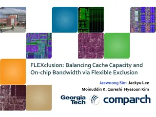
Archipelago: A Polymorphic Cache Design for Enabling Robust Near-Threshold Operation Amin Ansari,Shuguang Feng, Shantanu Gupta, and Scott Mahlke University of Michigan, Ann Arbor HPCA-17 February 16, 2011 University of Michigan University of Michigan University of Michigan Electrical Engineering and Computer Science Electrical Engineering and Computer Science Electrical Engineering and Computer Science
Matching Power Consumption and Utilization More than 50% of all computers Large SRAM structures limit the Min Vdd [Webber et. al.] More than 80% of times idle Logic cells can operate close to Vth DVS to improve battery life [Roth et. al.] Core i7 achieves 37% power reduction in idle state. University of Michigan University of Michigan University of Michigan 2 Electrical Engineering and Computer Science Electrical Engineering and Computer Science Electrical Engineering and Computer Science
Bit-Error-Rate for an SRAM Cell Extremely fast growth in failure rate with decreasing Vdd University of Michigan University of Michigan University of Michigan 3 Electrical Engineering and Computer Science Electrical Engineering and Computer Science Electrical Engineering and Computer Science
Our Goal Enabling DVS to push core s Vdd down to o Ultra low voltage region ( < 650mV ) o While preserving correct functionality of on-chip caches Proposing a highly flexible and FT cache architecture that can efficiently tolerate these SRAM failures Minimizing our overheads in high- power mode University of Michigan University of Michigan University of Michigan 4 Electrical Engineering and Computer Science Electrical Engineering and Computer Science Electrical Engineering and Computer Science
Archipelago (AP) This particular cache has only a single functional line. AP saves 6 out of 8 lines. By forming autonomous islands, data chunk 1 2 3 4 Island 1 Island 2 5 sacrificial line 6 7 8 sacrificial line University of Michigan University of Michigan University of Michigan Electrical Engineering and Computer Science Electrical Engineering and Computer Science Electrical Engineering and Computer Science
Baseline AP Architecture Two lines have collision, if they have at least one faulty chunk in Added modules: + Memory map + Fault map + MUXing layer Fault map address Sacrificial line Data line the same position (10 and 15 are collision free) There should be no collision between lines within a group [Group 3 (G3) contains lines 4, 10, and 15] Memory Map Input Address G3 First Bank Second Bank S Fault Map Two type of lines: + data line + sacrificial line MUXing layer - - Functional Block G3 University of Michigan University of Michigan University of Michigan 6 Electrical Engineering and Computer Science Electrical Engineering and Computer Science Electrical Engineering and Computer Science
AP with Relaxed Group Formation Sacrificial lines do not contribute to the effective capacity o We want to minimize the total number of groups Second Bank First Bank S S First Bank Second Bank S University of Michigan University of Michigan University of Michigan 7 Electrical Engineering and Computer Science Electrical Engineering and Computer Science Electrical Engineering and Computer Science
Semi-Sacrificial Lines First Bank Semi-sacrificial line guarantees the parallel access In contrast to a sacrificial line, it also contributes to the effective cache capacity Sacrificial line MUXing Layer Second Bank Semi-sacrificial line University of Michigan University of Michigan University of Michigan 8 Electrical Engineering and Computer Science Electrical Engineering and Computer Science Electrical Engineering and Computer Science
AP with Semi-Sacrificial Lines Memory Map Input Address G3 First Bank Second Bank S semi- sacrificial line way0 way1 way0 way1 Fault Map MUXing layer - G3 Functional Block University of Michigan University of Michigan University of Michigan 9 Electrical Engineering and Computer Science Electrical Engineering and Computer Science Electrical Engineering and Computer Science
AP Configuration We model the problem as a graph: o Each node is a line of the cache. o Edge when there is no collision between nodes A collision free group forms a clique o Group formation Finding the cliques To maximize the number of functional lines, we need to minimize the number of groups. o minimum clique cover (MCC). University of Michigan University of Michigan University of Michigan 10 Electrical Engineering and Computer Science Electrical Engineering and Computer Science Electrical Engineering and Computer Science
AP Configuration Example First Bank Second Bank 1 2 G1(1) 6 D G2(1) G2(S) 7 8 9 G2(3) G1(3) 3 4 5 G1(2) G1(S) 10 G2(2) G2(4) 10 1 Island or Group 2 7 2 9 4 Island or Group 1 8 5 3 6 Disabled University of Michigan University of Michigan University of Michigan 11 Electrical Engineering and Computer Science Electrical Engineering and Computer Science Electrical Engineering and Computer Science
Operation Modes High power mode (AP is turned off) There is no non-functional lines in this case Clock gating to reduce dynamic power of SRAM structures Low power mode o During the boot time in low-power mode BIST scans cache for potential faulty cells Processor switches back to high power mode Forms groups and configure the HW University of Michigan University of Michigan University of Michigan 12 Electrical Engineering and Computer Science Electrical Engineering and Computer Science Electrical Engineering and Computer Science
Evaluation Methodology Performance [DEC Alpha 21364] o SimAlpha that is based on SimpleScalar OoO [SPEC2K] Delay, power and area o Wattch and hot-leakage for power of processor o Artisan memory-compiler for our SRAM structures o CACTI for baseline on-chip caches (64KB, 2MB) o Synopsys design-compiler and power-compiler for Miscellaneous logic (e.g. bypass MUXes and comparators) Given set of cache parameters (e.g. Vdd) o Monte Carlo (with 1000 iterations) using our modified MCC o Determining disabled portion of caches (for 99% yield) University of Michigan University of Michigan University of Michigan 13 Electrical Engineering and Computer Science Electrical Engineering and Computer Science Electrical Engineering and Computer Science
Minimum Achievable Vdd University of Michigan University of Michigan University of Michigan 14 Electrical Engineering and Computer Science Electrical Engineering and Computer Science Electrical Engineering and Computer Science
Overheads Overheads for L1 and L2 caches o 10T used to protect the fault map, tag array, and memory map fault map (10T) miscellaneous logic memory map (10T) tag overhead (10T) 14 12 Percentage of Overhead 10 8 High Power Mode 6 4 2 0 L1 area L2 area L1 leakage power L2 leakage power L1 dynamic power L2 dynamic power University of Michigan University of Michigan University of Michigan 15 Electrical Engineering and Computer Science Electrical Engineering and Computer Science Electrical Engineering and Computer Science
Performance Loss One extra cycle latency for L1 and 2 cycles for L2 University of Michigan University of Michigan University of Michigan 16 Electrical Engineering and Computer Science Electrical Engineering and Computer Science Electrical Engineering and Computer Science
Summary of Benefits Larger leakage power savings for deeper technology nodes University of Michigan University of Michigan University of Michigan 17 Electrical Engineering and Computer Science Electrical Engineering and Computer Science Electrical Engineering and Computer Science
Comparison with Alternative Methods 100 10T Recently Proposed 66% area overhead Conventional Cache Area Overhead (%) ZC SEC- DED Row Red ECC-2 10 AP BF Disabled: 25% Disabled: 9% 1 0.5 1 Power (at minimum Vdd) Normalized to Archipelago 1.5 2 2.5 3 University of Michigan University of Michigan University of Michigan 18 Electrical Engineering and Computer Science Electrical Engineering and Computer Science Electrical Engineering and Computer Science
Conclusion DVS is widely used to deal with high power dissipation o Minimum achievable voltage is bounded by SRAM structures We proposed a highly flexible cache architecture o To tolerate failures when operating in near-threshold region Using our approach o Vdd of processor can be reduced to 375mV o 79% dynamic power saving and 51% leakage power saving o < 10% area overhead and performance overheads University of Michigan University of Michigan University of Michigan 19 Electrical Engineering and Computer Science Electrical Engineering and Computer Science Electrical Engineering and Computer Science
Thank You http://cccp.eecs.umich.edu University of Michigan University of Michigan University of Michigan 20 Electrical Engineering and Computer Science Electrical Engineering and Computer Science Electrical Engineering and Computer Science


")