Power FET Structures: DMOS and VMOS Applications
"Explore the functionalities and applications of Double-diffused MOSFET (DMOS) and Vertical MOSFET (VMOS) structures in handling significant power levels. Learn about their unique designs, characteristics, and applications in various industries such as automotive control, power supplies, and inkjet print heads."

Download Presentation

Please find below an Image/Link to download the presentation.
The content on the website is provided AS IS for your information and personal use only. It may not be sold, licensed, or shared on other websites without obtaining consent from the author. If you encounter any issues during the download, it is possible that the publisher has removed the file from their server.
You are allowed to download the files provided on this website for personal or commercial use, subject to the condition that they are used lawfully. All files are the property of their respective owners.
The content on the website is provided AS IS for your information and personal use only. It may not be sold, licensed, or shared on other websites without obtaining consent from the author.
E N D
Presentation Transcript
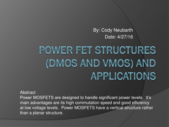
By: Cody Neubarth Date: 4/27/16 POWER FET STRUCTURES POWER FET STRUCTURES (DMOS AND VMOS) AND (DMOS AND VMOS) AND APPLICATIONS APPLICATIONS Abstract Power MOSFETS are designed to handle significant power levels. It s main advantages are its high commutation speed and good efficiency at low voltage levels. Power MOSFETS have a vertical structure rather than a planar structure.
Outline DMOS What is a DMOS? DMOS Structure DMOS Applications VMOS What is a VMOS? VMOS Structure VMOS Applications
DMOS what is it? Double-diffused MOSFET (DMOS) A power MOSFET in which the source and channel regions are formed using a double diffusion process Used in switching applications with high voltage and high frequencies
DMOS Structure p-substrate region and the n+ source contact are diffused through a common window defined by edge of gate p-base region is diffused deeper than the n+ source Result: difference in the lateral diffusion distance between p-base and the source defines the surface channel length http://www.circuitstoday.com/wp-content/uploads/2010/07/DMOS-Structure.jpg
DMOS Structure Electrons enter the source terminal and flow laterally through the inversion layer under the gate to the n-drift region. Once here the electrons flow vertically through the n-drift region to the drain terminal. Conventional current direction is from the drain to the source. Cross-section of DMOS Semiconductor Physics and Devices textbook by Donald A. Neamen
DMOS Structure DMOS similar to BJT Important characteristic are the breakdown voltage and the on-resistance A lightly doped drift region between the drain contact and the channel region helps ensure a very high breakdown voltage
DMOS Structure The n-drift region must be moderately doped so that the drain breakdown voltage is large The thickness of the n-drift region should be as thin as possible in order to minimize drain resistance
Applications of DMOS Automotive Control Applications Power supplies Inkjet print heads
VMOS what is it? Named after V-shaped gate region Vertical MOSFET with high current handling capability as well as high blocking voltage Consists of a double diffused n+/p layer, which is cut by a V-shaped groove Metalized area over the V-groove controls the current flow in the P region
Structure of VMOS V-groove cuts through the double diffused layer creating two vertical MOSFETs Short gate length, which is determined by thickness of p-type layer Vertical structure allows for use of low-doped drain region which results in a high blocking voltage http://ecee.colorado.edu/~bart/book/book/chapter7/ch7_8.htm#7_8_2
Structure of VMOS V shape allows device to deliver higher amount of current from source to the drain Shape of the depletion region creates a wider channel The V-shaped gate increases the cross- sectional area of source-to-drain path
Structure of VMOS Main drawback of VMOS: Structure is more complicated than traditional FETs, making it more expensive. UMOS More cross-sectional surface area
Application of VMOS Hi-fi audio power amplifiers Broadband high frequency amplifiers Switching power amplifiers
Summary Power MOSETS have a vertical structure of both the DMOS and VMOS Used in a variety of applications that desire increased switching speeds and a variety of voltage levels Doping and channel lengths contribute to the characteristic of each of these MOSFETs
References "Double-Diffused MOS (DMOS)." Electronic Circuits and Diagrams. N.p., 22 July 2011. Web. 216 Apr. 2016. John. "V-Groove MOS (VMOS)." Circuits Today. 2015 Circuits Today, Feb. 9, 2011. Web. 15 April 2016. Neamen, Donald A. "15.5 Power MOSFETs." Semiconductor Physics and Devices: Basic Principles fourth edition. New York, NY: McGraw-Hill, 2012. N. page 684-685. Print. Poole Ian. "VMOS Field Effect Transistor." Radio-Electronics. Adrio Communications Ltd. Web. 13 April 2016. "Power MOSFET." Wikipedia. 29 December 2015. Web. 13 April 2016. Van Zeghbroeck, Bart. "Chapter 7: MOS Field-Effect- Transistors." Power MOSFETs. N.p., 2011. Web. 16 April 2016.
Five Key Points Main advantages are high commutation speed and good efficiency at low voltages Power MOSFETS have a vertical structure rather than planar DMOS uses double diffusion process V-shaped gate in VMOS increases cross- sectional area of the source-to-drain path Most important characteristics are the breakdown voltage and the on-resistance