Power System Dynamics and Stability Overview
This lecture series covers various topics in power system dynamics and stability, presented by Prof. Tom Overbye from the University of Illinois at Urbana-Champaign. Topics include electromagnetic transients, synchronous machine modeling, transient stability, and more. The content also delves into modeling caution in engineering and showcases Prof. Overbye's professional and personal background.

Download Presentation

Please find below an Image/Link to download the presentation.
The content on the website is provided AS IS for your information and personal use only. It may not be sold, licensed, or shared on other websites without obtaining consent from the author.If you encounter any issues during the download, it is possible that the publisher has removed the file from their server.
You are allowed to download the files provided on this website for personal or commercial use, subject to the condition that they are used lawfully. All files are the property of their respective owners.
The content on the website is provided AS IS for your information and personal use only. It may not be sold, licensed, or shared on other websites without obtaining consent from the author.
E N D
Presentation Transcript
ECE 576 Power System Dynamics and Stability Lecture 2: Overview and Electromagnetic Transients Prof. Tom Overbye Dept. of Electrical and Computer Engineering University of Illinois at Urbana-Champaign overbye@illinois.edu 1
About Me Professional Received BSEE, MSEE, and Ph.D. all from University of Wisconsin at Madison (83, 88, 91) Worked for eight years as engineer for an electric utility (Madison Gas & Electric) Have been at UI since 1991, doing teaching and doing research in the area of electric power systems Developed commercial power system analysis package, known now as PowerWorld Simulator. This package has been sold to about 600 different corporate entities worldwide DOE investigator for 8/14/2003 blackout
About Prof. Tom Overbye Nonprofessional Married to Jo Have three children Tim age 19 Hannah age 16 (almost 17!) Amanda age 14 Live in country by Homer We ve homeschooled our kids all the way through, with Tim now starting his second semester at UIUC in mechanical engineering 3
My Kids 4
Course Topics 1. Overview 2. Electromagnetic transients 3. Synchronous machine 4. Excitation and governor modeling 5. Single machine 6. Time-scales and reduced-order models 7. Multi-machine 8. Transient Stability 9. Linearization, small signal 10.Power system stabilizer design 11.Energy function methods
Power Systems Aircraft Automobiles Standby power sources Electric utilities Mechanical prime movers Electrical generators Electrical network Electrical loads
Power System Time Frames Image source: P.W. Sauer, M.A. Pai, Power System Dynamics and Stability, 1997, Fig 1.2, modified 7
Modeling Cautions! "All models are wrong but some are useful," George Box, Empirical Model-Building and Response Surfaces, (1987, p. 424) Models are an approximation to reality, not reality, so they always have some degree of approximation Box went on to say that the practical question is how wrong to they have to be to not be useful A good part of engineering is deciding what is the appropriate level of modeling, and knowing under what conditions the model will fail Always keep in mind what problem you are trying to solve! 8
Transient Stability Example 1 1996: Transient Stability Model Errors Lead to Blackouts 9
Transient Stability Example 2 We ve come a long ways since 1996 towards improved simulations. Still, a finding from the 2011 Blackout is the simulations didn t match the actual system response and need to be improved. Source: Arizona-Southern California Outages on September 8, 2011 Report, FERC and NERC,April 2012 10
Models and Their Parameters Models and their parameters are often tightly coupled The parameters for a particular model might have been derived from actual results on the object of interest Changing the model (even correcting an "incorrect" simulation implementation) can result in unexpected results! Using a more detailed simulation approach without changing the model can also result in incorrect results More detailed models are not necessarily more accurate 11
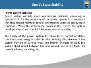
Static versus Dynamic Analysis Statics versus dynamics appears in many fields An equilibrium point is a point at which the model is not changing Real systems are always changing, but over the time period of interest an unchanging system can be a useful approximation Static analysis looks at how the equilibrium points change to a change in the model Power system example is power flow Dynamic analysis looks at how the system responds over time when it is perturbed away from an equilibrium point Power system example is transient stability 12
Slow versus Fast Dynamics Key analysis question in setting up and solving models is to determine the time frame of interest Values that change slowing (relative to the time frame of interest) can be assumed as constant Power flow example is the load real and reactive values are assumed constant (sometimes voltage dependence is included) Values that change quickly (relative to the time frame of interest) can be assumed to be algebraic A generator's terminal voltage in power flow is an algebraic constraint, but not in transient stability In power flow and transient stability the network power balance equations are assumed algebraic 13
Positive Sequence versus Full Three-Phase Large-scale electrical systems are almost exclusively three-phase. Common analysis tools such as power flow and transient stability often assume balanced operation This allows modeling of just the positive sequence though full three-phase models are sometimes used particularly for distribution systems Course assumes knowledge of sequence analysis Other applications, such as electromagnetic transients (commonly known as electromagnetic transients programs [EMTP]) consider the full three phase models 14
Course Coverage Course is focused on the analysis of the dynamics and stability of high voltage power systems Some consideration of general solution methods, some consideration of power system component modeling in different time frames, and some consideration of using tools to solve example larger-scale power system problems Course seeks to strike a balance between the theoretical and the applied 15
PowerWorld Simulator Class will make extensive use of PowerWorld Simulator. If you do not have a copy of v17, the free 42 bus student version is available for download at http://www.powerworld.com/gloversarmaoverbye Start getting familiar with this package, particularly the power flow basics. Transient stability aspects will be covered in class Free training material is available at http://www.powerworld.com/training/online-training 16
Power Flow Versus Dynamics The power flow is used to determine a quasi steady- state operating condition for a power system Goal is to solve a set of algebraic equations g(x) = 0 Models employed reflect the steady-state assumption, such as generator PV buses, constant power loads, LTC transformers Dynamic analysis is used to determine how the system changes with time, usually after some disturbance perturbs it away from a quasi-steady state equilibrium point 17
Example: Transient Stability Transient stability is used to determine whether following a disturbance (contingency) the power system returns to a steady-state operating point Goal is to solve a set of differential and algebraic equations, dx/dt = f(x,y), g(x,y) = 0 Starts in steady-state, and hopefully returns to steady-state. Models reflect the transient stability time frame (up to dozens of seconds), with some values assumed to be slow enough to hold constant (LTC tap changing), while others are still fast enough to treat as algebraic (synchronous machine stator dynamics, voltage source converter dynamics). 18
Physical Structure Power System Components P. Sauer and M. Pai, Power System Dynamics and Stability 19
Physical Structure Power System Components Mechanical System Electrical System Stabilizer Load Relay Line Relay Exciter Network control Supply control Pressure control Speed control Voltage Control Load control Fuel Source Furnace and Boiler Turbine Generator Machine Network Loads Load Char. V, I P, Q Fuel Steam Torque Governor 20
Electromagnetic Transients The modeling of very fast power system dynamics (much less than one cycle) is known as electromagnetics transients program (EMTP) analysis Covers issues such as lightning propagation and switching surges Concept originally developed by Prof. Hermann Dommel for his PhD in the 1960's (now emeritus at Univ. British Columbia) After his PhD work Dr. Dommel worked at BPA where he was joined by Scott Meyer in the early 1970's Alternative Transients Program (ATP) developed in response to commercialization of the BPA code 22
Transmission Line Modeling In power flow and transient stability transmission lines are modeled using a lumped parameter approach Changes in voltages and current in the line are assumed to occur instantaneously Transient stability time steps are usually a few ms (1/4 cycle is common, equal to 4.167ms for 60Hz) In EMTP time-frame this is no longer the case; speed of light is 300,000km/sec or 300km/ms or 300m/ s Change in voltage and/or current at one end of a transmission cannot instantaneously affect the other end 23
Incremental Transmission Line Modeling Define the receiving end as bus m (x=0) and the sending end as bus k (x=d) i t R xi + L x = v ( ) ( ) G x v C x = + + + i v v v t 24
Incremental Transmission Line Modeling We are looking to determine v(x,t) and i(x,t) i t = + Substitute v x R i L Into the equation for i G v G x + and divide both by i L x t i x v t R xi = + + + C 2 i t i L x + C R x 2 t 25
Incremental Transmission Line Modeling Taking the limit we get lim v i v = + R i L = x t 0 x x lim i i v = v = + G C 0 x x x t Some authors have a negative sign with these equations; it just depends on the direction of increasing x; note values are function of both x and t 26
Special Case 1 C' = G' = 0 (neglect shunts) di ( ) ( , 0 ) x x = + + , v x t v t R L i dt This just gives a lumped parameter model, with all electric field effects neglected 27
Special Case 2: Wave Equation The lossless line (R'=0, G'=0), which gives v i i L C x t x v t = = , This is the wave equation with a general solution of ( ( ) ( 1 , c p c v x t z f x v t z f ) ( ) ( ) Zc is the characteristic impedance and vp is the velocity of propagation = f x v t + , i x t f x v t 1 2 p p ) ( 1 ) = + x v t 2 p L C = = / , z v c p L C 28
Special Case 2: Wave Equation This can be thought of as two waves, one traveling in the positive x direction with velocity vp, and one in the opposite direction The values of f1 and f2 depend upon the boundary (terminal) conditions ( ( ) ( 1 , c p c v x t z f x v t z f ) ( ) ( ) = f x v t + , i x t f x v t 1 2 p p ) ( 1 ) = + x v t 2 p L C = = / , z v c p L C 29
Calculating vp To calculate vp for a line in air we go back to the definition of L' and C' (covered in a course like 476) D L C r 2 ln 0 0 = = ' ln , ' D 2 ' r 1 1 1 = = = v c p ' ' L C D D ln ln ' ' r r 0 0 D D ln ln r r With r'=0.78r this is very close to the speed of light 30
Important Insight The amount of time for the wave to go between the terminals is d/vp= seconds To an observer traveling along the line with the wave, x+vpt, will appear constant What appears at one end of the line impacts the other end seconds later ( ( ) ( ( ) ( ) ( 2 , , 2 c c v x t z i x t z f Both sides of the bottom equation are constant when x+vpt is constant ) ( ) ( ) = f x v t + , i x t f x v t 1 2 p p ) ( + ) = + , v x t z f x v t z f x v t 1 2 c p c p ) + = x v t p 31
Determining the Constants If just the terminal characteristics are desired, then an approach known as Bergeron's method can be used. Knowing the values at the receiving end m (x=0) we get ( ( ) ( ( ) ( ( 1 2 ( ) m c p c v t z f v t z f ) ( ) ( ) = f x v t + , i x t f x v t 1 2 p p This can be used to eliminate f1 ) ( ) = + , v x t z f x v t z f x v t 1 2 c p c p ) ( ( ) = = ( ) t 0, i i t f v t f v t 1 2 m p p ) ) = v t p 32
Determining the Constants Eliminating f1 we get ( ) m v t ( ) ( ) = z f v t z f v t 1 2 c p c p m t v z v ( ) ( ) ( ) = + f v t f v t 1 2 p p c ( ) = m ( ) t 2 i f v t 2 m p z c 33
Determining the Constants To solve for f2 we need to look at what is going on at the sending end (i.e., k at which x=d) = d/vp seconds in the past = = = d v d v d v + i t f d v t f d v t 1 2 k p p p p p d v ( ) ( ) 2 i t f d v t f v t 1 2 k p p p d v ( ) ( ) 2 v t z f d v t z f v t 1 2 k c p c p p 34
Determining the Constants Dividing vk by zc, and then adding it with ik gives + = v z d v d v ( ) k 2 i t t f v t 2 k p p c p Then substituting for f2 in im gives ( ) m c z ( ) t v 1 z d v d v = + + m i t i t v t k k p c p 35
Equivalent Circuit Representation The receiving end can be represented in circuit form as ( ) t z v I 1 z d v d v ( ) t = + + m i i t v t m m k k c p c p Notice that the voltage and current at the other end of the line, from seconds in the past, just look like a current source 36
Repeating for the Sending End The sending end has a similar representation Both ends of the line are represented by Norton equivalents 1 d d = I m i t v t k m v z v p c p 1 d d = + I i t v t m k k v z v p c p 37
Lumped Parameter Model In the special case of constant frequency, book shows the derivation of the common lumped parameter model 38
Including Line Resistance An approach for adding line resistance, while keeping the simplicity of the lossless line model, is to just to place of the resistance at each end of the line Another, more accurate approach, is to place at each end, and in the middle Standalone resistance, such as modeling the resistance of a switch, is just represented as an algebraic equation 1 R ( ) = , k m i v v k m 39