Power Systems: Physics and Models
Delve into the physics behind power systems to develop equations and models that accurately represent real-world behavior. Explore topics such as three-phase power, transformer models, symmetrical components, and fault calculations to optimize system efficiency and reliability. Gain insights into transmission line models, per unit system, and power definitions to ensure effective power system operation and protection.

Download Presentation

Please find below an Image/Link to download the presentation.
The content on the website is provided AS IS for your information and personal use only. It may not be sold, licensed, or shared on other websites without obtaining consent from the author.If you encounter any issues during the download, it is possible that the publisher has removed the file from their server.
You are allowed to download the files provided on this website for personal or commercial use, subject to the condition that they are used lawfully. All files are the property of their respective owners.
The content on the website is provided AS IS for your information and personal use only. It may not be sold, licensed, or shared on other websites without obtaining consent from the author.
E N D
Presentation Transcript
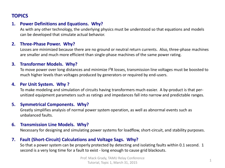
TOPICS 1. Power Definitions and Equations. Why? As with any other technology, the underlying physics must be understood so that equations and models can be developed that simulate actual behavior. 2. Three-Phase Power. Why? Losses are minimized because there are no ground or neutral return currents. Also, three-phase machines are smaller and much more efficient than single-phase machines of the same power rating. 3. Transformer Models. Why? To move power over long distances and minimize I R losses, transmission line voltages must be boosted to much higher levels than voltages produced by generators or required by end-users. 4. Per Unit System. Why ? To make modeling and simulation of circuits having transformers much easier. A by-product is that per- unitized equipment parameters such as ratings and impedances fall into narrow and predictable ranges. 5. Symmetrical Components. Why? Greatly simplifies analysis of normal power system operation, as well as abnormal events such as unbalanced faults. 6. Transmission Line Models. Why? Necessary for designing and simulating power systems for loadflow, short-circuit, and stability purposes. 7. Fault (Short-Circuit) Calculations and Voltage Sags. Why? So that a power system can be properly protected by detecting and isolating faults within 0.1 second. 1 second is a very long time for a fault to exist - long enough to cause grid blackouts. Prof. Mack Grady, TAMU Relay Conference Tutorial, Topic 1, March 31, 2015 1
1. Power Definitions and Equations, cont. As with any other technology, the underlying physics must be understood so that equations and models can be developed that simulate actual behavior. Instantaneous power p(t) flowing into the box + = V t v o sin( ) ( + = I t i o i (t ) ( ) sin( ), ) t + Circuit in a box, two wires t v (t ) = ( ) ( ) ( ) p t v t i t i I (t sin( ) = = + + ( ) ( ) ( ) sin( ) ) p t v t i t V t t o o zero average + + cos( ) cos( 2 ) t o = ( ) p t VI peak 2 1 VI V I + t T = = = o cos( ) cos( ) ( ) P p t dt avg 2 T 2 2 t o Average power Pavg flowing into the box rms = cos( ) avg P rms V I rms Power factor Prof. Mack Grady, TAMU Relay Conference Tutorial, Topic 1, March 31, 2015 2
1. Power Definitions and Equations. As with any other technology, the underlying physics must be understood so that equations and models can be developed that simulate actual behavior. + + ) vR (t iR (t ) ? ? = ? ??? ?? , ? ? = ?? ??? ?? , ? ? in phase with ? ? ( ) v t = ( ) R i t R R + + ) vL (t iL (t ) ? ? = ? ??? ?? , ? ? = ?? ??? ?? , ? ? lags ? ? by 90 ( ) di t = ( ) vL t L dt + + ) vC (t iC (t ) ( ) dv t ? ? = ? ??? ?? , ? ? = ?? ??? ?? , ? ? leads ? ? by 90 ( = ) iC t C dt Prof. Mack Grady, TAMU Relay Conference Tutorial, Topic 1, March 31, 2015 3
1. Power Definitions and Equations, cont. Thanks to Charles Steinmetz, Steady-State AC problems are greatly simplified with phasor analysis because differential equations are replaced by complex numbers Time Domain Frequency Domain ~ v t ( ) V R R = = = =~ = = i t ( ) Resistor Z R R R R I R voltage leads current ~ di t ( ) V L = = vL t L ( ) = =~ = = j Inductor Z L L dt I L current leads voltage ~ dv t ( ) V ~ 1 = = iC t C ( ) C = = = = Z Capacitor C dt j C I C Prof. Mack Grady, TAMU Relay Conference Tutorial, Topic 1, March 31, 2015 4
1. Power Definitions and Equations, cont. Voltage and Current Phasors for R s, L s, C s ~ V ~ Voltage and Current in phase ~ ~ R = = = = = = Z R V R I , Resistor Q = 0 R R R I R Voltage leads Current by 90 ~ V ~ ~ ~ L = = = = j = = j Z L V L I , Q > 0 Inductor L L L I L ~ ~ Current leads Voltage by 90 V ~ I 1 ~ C C = = = = = = Z V , Capacitor Q < 0 C C j j C C I C Prof. Mack Grady, TAMU Relay Conference Tutorial, Topic 1, March 31, 2015 5
1. Power Definitions and Equations, cont. Converting Time Domain Waveforms to Phasor Domain Using a cosine reference, Voltage cosine has peak = 100V, phase angle = -90 Current cosine has peak = 50A, phase angle = -135 100 ~ V V = Phasors 50 ~ = = I A 135 90 , 2 2 100 V I = cos( ) Pavg 80 2 2 60 100 50 ( ) ) = 135 cos 90 ( P 40 avg 2 2 20 Voltage Current 0 0 30 60 90 120 150 180 210 240 270 300 330 360 -20 100 50 ( ) = cos 45 P -40 avg 2 2 -60 = 1767 Pavg W -80 -100 Prof. Mack Grady, TAMU Relay Conference Tutorial, Topic 1, March 31, 2015 6
1. Power Definitions and Equations, cont. Circuit analysis using the Nodal Method. Write KCL equations at major nodes 1 and 2, and solve for phasor voltages V1 and V2 . + + 2 2 3 4 j ~ ~ V1 1 V V2 2 V Reference 100 20 1 1 4 2 1 j 1 1 1 j 1 j 1 100 20 ~ 1 V + + ~ V 100 20 1 1 100 1 1 4 3 2 2 j + + 4 ~ V 20 1 1 = + 1 + 100 2 ~ V 2 2 j = ~ 4 1 1 1 1 100 j 20 2 1 1 = 2 V + + 1 1 20 2 1 D 2 2 2 2 j 1 j 1 1 1 1 1 1 = + + + + 1 D 1 100 20 4 3 2 2 2 2 2 j 1 1 j 1 1 1 1 1 1 2 4 j 1 = + + + + 1 D 20 2 1 1 100 20 4 3 2 2 2 2 2 j + + 100 1 2 2 j ~ 4 j = V 1 1 2 + + D 100 20 1 2 2 j ~ Prof. Mack Grady, TAMU Relay Conference Tutorial, Topic 1, March 31, 2015 D 2 = V 7 1 1 100 20 4 j 1 1 + + 1 100 20 2 2 j ~ = V 2 D
1. Power Definitions and Equations, cont. Active power Pavg and reactive power Q form a power triangle V I V I = = cos( ), Pavg sin( ), Q 2 2 2 2 = V ~ ~ ( ) * * = + = I = S P jQ I V VI V~ = =V Complex power S Projection of S on the imaginary axis ( Q ) ( ) I~ = = I P Projection of S on the real axis cos( ) is the power factor Prof. Mack Grady, TAMU Relay Conference Tutorial, Topic 1, March 31, 2015 8
1. Power Definitions and Equations, cont. Resistor ~ * V 2 2 V V V ~ = + = = = S P jQ * Z Z R Thus 2 V = = = 2 , 0 P I R Q Alternatively, R Z I ~ ~ * = + = = = 2 2 S P jQ I I Z I R Inductor S = ~ * V 2 2 2 V V V V ~ + = = = = P jQ j ~ I * Z Z j L L Thus 2 V = = = 2 , 0 P Q LI Alternatively, Z I L ~ * = + = = = 2 2 S P jQ I Z j LI Inductor consumes reactive power Capacitor S = ~ V * V 2 2 V V ~ + = = = = 2 P jQ j CV 1 j * Z Z Thus C 2 I Alternatively, = = = 2 , 0 P Q CV Z I 1 ~ ~ I C * = + = = = 2 2 S P jQ I j LI Capacitor produces reactive power j C Always use rms values of voltage and current in the above equations Prof. Mack Grady, TAMU Relay Conference Tutorial, Topic 1, March 31, 2015 9
1. Power Definitions and Equations, cont. IB Question: Why is the sum of power out of a node = 0? Answer: KCL and conservation of power IA IC Question: What about reactive power Q? Answer: It depends. Question: Can you be a bit more specific? Answer: Unlike P, there is no physical for Q to be conserved. ~ I ~ I ~ I + + = 0 A B C ( ( I ) 0 = ~ V ~ I ~ I ~ I ) + + A B C When voltage and current are not sinusoidal, then cross products of voltage and current exist and Q is not conserved. ~ V ~ ~ I ~ I *= + + 0 A B C But power systems are mostly sinusoidal, so as shown on the right with phasors, both P and Q are conserved. + + + + + = 0 P jQ P jQ P jQ A A B B C C + + = 0 P P P A B C + + = 0 Q Q Q A B C Prof. Mack Grady, TAMU Relay Conference Tutorial, Topic 1, March 31, 2015 10