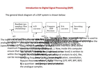
Power Systems: Sources, Converters, and Loads
A power system consists of power sources, converters, and loads. Power sources provide electric power, converters alter power characteristics, and loads consume power. Different types of power sources, such as bench power supplies and batteries, have specific functions. Loads vary from sensors to motors, each contributing to the system's total power consumption. It is crucial to supply the correct voltage and current to prevent component damage. Electric power converters are used to adapt supply voltages for interfacing different components within a system.

Download Presentation

Please find below an Image/Link to download the presentation.
The content on the website is provided AS IS for your information and personal use only. It may not be sold, licensed, or shared on other websites without obtaining consent from the author. If you encounter any issues during the download, it is possible that the publisher has removed the file from their server.
You are allowed to download the files provided on this website for personal or commercial use, subject to the condition that they are used lawfully. All files are the property of their respective owners.
The content on the website is provided AS IS for your information and personal use only. It may not be sold, licensed, or shared on other websites without obtaining consent from the author.
E N D
Presentation Transcript
Simple Power Systems LSU rev20AUG2020 L30.01 Power Systems 1
What is a Power System? A power system is a system that which generates, stores, or distributes power. It typically contains three parts power sources, power converters, and loads. Power Source Power Sources are sources of electric power that provide power to connected systems Power Converters are devices that alter the characteristics of electric power delivered to the load. Loads are any device that consumes electric power within a given system Power Converter Load LSU rev20AUG2020 L30.01 Power Systems 2
Power Sources A power supply is a device that supplies electric power to a load. They may supply voltage in either AC or DC. Power supplies are limited in the amount of power that can be distributed at a time. Some supplies have overdraw protections to prevent damage to components. Some supplies do not have overdraw protection and may overheat when too much power is drawn! LSU rev20AUG2020 L30.01 Power Systems 3
Power Sources Bench Power Supply Bench power supplies are power supplies that output a wide range of voltages and currents for bench top testing. They have adjustable, regulated output voltages and typically include a current limiting feature. LSU rev20AUG2020 L30.01 Power Systems 4
Power Sources Batteries Batteries are power supplies with one or more cells that store energy chemically. They come in many different forms and packages. Batteries are often used in experiments where power cannot be reliably supplied from external sources such as the power grid. LSU rev20AUG2020 L30.01 Power Systems 5
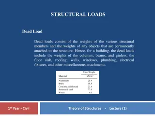
Loads A load is any device in a system that consumes electric power. It may be a sensor, a motor, a regulator, or an electronics board. It is important to identify all loads within a system to calculate how much power must be supplied. Each load contributes to the total power consumption. Often, the power consumed by a load in a system is released as heat. This means components that consume more power will generate more heat. This is important for thermal calculations. LSU rev20AUG2020 L30.01 Power Systems 6
Interfacing Power Systems Many loads have different requirements on the voltage or current. Supplying the incorrect voltage or current may result in irregular payload behavior, malfunctioning components, or, in extreme cases, damaged or destroyed components. In many cases, power supplies do not supply the correct voltages needed to run every component. Electric power converters are used to change the supply voltage into the necessary voltages. LSU rev20AUG2020 L30.01 Power Systems 7
Power Converters Electric power converters are electronic devices that the convert a voltage level of one source to another voltage level. The input voltage and output voltage of the converter varies greatly component to component. They have different tolerances and specifications. It is important to consult the datasheet of power converters to determine what voltages are required for proper operation. LSU rev20AUG2020 L30.01 Power Systems 8
Linear Regulators Linear regulators are step-down converters that output a steady DC voltage. They take a higher voltage and convert it into a lower stable voltage. Linear regulators require a minimum amount of voltage in order to function. This minimum voltage can be found on the datasheet. Linear regulators do not follow the same rules of power consumption as DC/DC converters. Their power consumption follows the current drawn from the device. They consume significantly more power as a result. LSU rev20AUG2020 L30.01 Power Systems 9
DC/DC Converters DC/DC converters convert a source of DC voltage from one voltage level to another. They are capable of outputting low or high voltage depending on the model. DC/DC converters create output noise due to their method of power conversion. This noise can be mitigated (but not completely removed) by filtering. DC/DC converters typically require a larger voltage differences between input and output voltage than linear regulators. LSU rev20AUG2020 L30.01 Power Systems 10
Converter Efficiency Each power converter acts as both a supply and a load. Power Loss Input Power Output Power In order to convert the supply voltage into another voltage, some power must be consumed by the regulator itself. Power Converter =??????? ?????? =??????+ ????? ?????? The efficiency of a regulator is the ratio of supplied power to consumed power. LSU rev20AUG2020 L30.01 Power Systems 11
ExampleLinear Regulator Suppose you have the following setup: 12 V to 5 V Linear Regulator 5V Load (300 mA) 12 V Battery The load draws 300 mA at 5V from the converter. Using the power equation, we calculate a load consumption of 1.5W Input Voltage The linear regulator follows the power equation on the right. The regulator has a 12V input and 300 mA output. ?? ???= ??? ???? Regulator Power Output Current The power consumption of the linear regulator, therefore, is 3.6W. This gives a total power consumption of 6.1W LSU rev20AUG2020 L30.01 Power Systems 12
ExampleDC/DC Converter Suppose you have the following setup: 12 V to 5 V DC/DC Converter 90% Efficiency 5V Load (300 mA) 12 V Battery The load draws 300 mA at 5V from the converter. Using the power equation, we calculate a load consumption of 1.5W Power consumed by load ??????=????? The power converter has a 90% efficiency. Using the rearranged efficiency equation on the right, we can calculate a total power consumption of 1.7W Efficiency Total power consumed Subtracting the load consumption leaves 0.2W. This is the power consumed by the DC/DC converter. LSU rev20AUG2020 L30.01 Power Systems 13
Power System Diagrams With complex systems, it is useful to visually represent the flow of power from the power source to the individual loads. This can be accomplished by power system diagrams. Power system diagrams show each power source, converter, and load for a given system and how each component connects to each other. It visually represents the the power interfaces. LSU rev20AUG2020 L30.01 Power Systems 14
Simple Power Block Diagram 1. Identify power sources and loads 2. Research each load s power requirements When in doubt, check the DATASHEET 3. List all required voltages and what loads require which voltages 4. Draw a block diagram showing each supply, converter, and load and how they are connected Battery (4x AA 6V) Linear Regulator (6V to 3.3V) Sensor (3.3V) LSU rev20AUG2020 L30.01 Power Systems 15
Power Budgets A power budget is a table of all electronic components, their required voltages, their current draws, and their consumed power. It may also contain information on how long a component will be powered. Power budgets are used to ensure power is supplied for the duration of an experiment. It is also useful for determining which power supplies or converters should be used. LSU rev20AUG2020 L30.01 Power Systems 16
Power Budget Required Information To create a power budget, you require the following information: Mission duration The total amount of time the system will be powered. Maximum load current The peak current draw possible from a device. This can be found on the components datasheet or measured directly Average load current The typical or average current draw from a device. This can be found on the components datasheet or measured directly Voltage levels The voltage required for power. This can be found on the datasheet or component listing. Duty cycle Percent or ratio of a specified period of time that a device is active or powered. LSU rev20AUG2020 L30.01 Power Systems 17
Period Duration and Duty Cycle Duty cycle is defined as the ratio of the time powered over a specified period of time. The duration of the period is the period duration. To determine the duty cycle of a component, calculate how much time the particular component must be powered or in high power mode during a given period. The duty cycle is the ratio of this calculated time to the period duration. ???????? ??????? ???? ????? = LSU rev20AUG2020 L30.01 Power Systems 18
Power Budget Example For the following example, the system on the right will be used. It is a simplified version of a beacon used during flight. It must run for 8 hours Furthermore, we know the following information: The Flight Computer draws 50mA continuously The GPS Receiver draws 140 mA continuously The transmitter draws 80 mA when in standby The transmitter draws 1050mA when transmitting The transmission lasts 2 seconds. Transmission occurs once every 30 seconds LSU rev20AUG2020 L30.01 Power Systems 19
Power Budget Example Duty Cycle For components with two or more states, you must calculate the duty cycle for each state.. The flight computer, GPS receiver, and power converter run continuously and do not have multiple states. Thus, they each have a duty cycle of 100% In this example, the transmitter has two states transmit and standby. The transmitter will draw its max current for 2 seconds every 30 seconds. If we set the period duration to 30 seconds, we find that the transmitter has a duty cycle of roughly 7% ???? ????? ???????? =????????? 2 ??????? 30 ???????= 6.67% 7% = ??????? The standby duty cycle will be the time it doesn t transmit. This makes the standby duty cycle 93% LSU rev20AUG2020 L30.01 Power Systems 20
Power Budget Example Constant Draw Devices Power consumption for devices with 100% duty cycle is calculated with the power equation ? = ? ?. In this example, we have three devices with 100% duty cycle the flight computer, the GPS receiver, and the power converter. The flight computer draws 50mA at 5V for a power consumption of 0.25W The GPS receiver draws 140mA at 5V for a power consumption of 0.7W From the earlier example (Slide 13), we know the power converter will consume 0.2W of power or ~17 mA at 12V. LSU rev20AUG2020 L30.01 Power Systems 21
Power Budget Example Duty Cycle Current Current Draw When the duty cycle is not 100%, the amount of power consumed over the given time period is not equal the power equation. A correction must be made to reflect the actual power consumption. This is done by calculating the duty cycle current. ??????= ?? ???? ????? To calculate the duty cycle current, multiply the current by the duty cycle of the device. This should be repeated for every state the device will enter. Duty cycle current In this example, the transmitter remains in standby 93% of the time and in transmit 7% of the time. While in standby, the transmitter draws 80mA. While in transmit, it draws 1050mA. The duty cycle for standby and transmit is 75mA and 74mA, respectively. ????????= 80 mA 0.93 = 75 ?? ?????????= 1050 mA 0.07 = 74 ?? LSU rev20AUG2020 L30.01 Power Systems 22
Power Budget Example Capacity Calculations Duty cycle current is used to calculate the battery capacity that the power supply is required to supply. To calculate the required battery capacity, sum all the duty cycle currents together and multiply by the mission duration. Be sure to watch your units! Make sure all your values are in hours and milliamps before beginning your calculations! ????????(mA h)= ? ???? ?????? Required Battery Capacity Duty cycle current Mission duration LSU rev20AUG2020 L30.01 Power Systems 23
Assembling the Budget Once the power consumption of every device has been estimated, calculated, or measured, create a table to display all the information. Component Name Power Converter Flight Computer GPS Module Transmitter (Standby) Transmitter (Transmit) Total Duty Cycle Current 17 mA 50 mA 140 mA Power Consumed 200 mW 250 mW 700 mW Voltage Current Duty Cycle (%) 12 V 5 V 5 V 17 mA 50 mA 140 mA 100 100 100 5 V 80 mA 93 75 mA 372.5 mW 5 V 1050 mA 7 74 mA 367.5 mW 355 mA 1890 mW For an 8-hour mission duration, the example system requires 2,840 mA-hr of battery capacity. LSU rev20AUG2020 L30.01 Power Systems 24
Advanced Power Systems More advanced power systems focus on the control and monitoring of the power. They may also include protections to isolate sensitive devices or prevent cascading damage from failed components. Relays and switches are examples of components that are used to control the flow of power in systems. Fuses protect components from overvoltage and overcurrent conditions. LSU rev20AUG2020 L30.01 Power Systems 25