Power Triangle and Reactive Power in Electrical Systems
Discover the hidden insights about the Power Triangle and Reactive Power in electrical systems, including how to compensate for reactive loads, different power factors, and the mathematical principles behind power calculations.

Download Presentation

Please find below an Image/Link to download the presentation.
The content on the website is provided AS IS for your information and personal use only. It may not be sold, licensed, or shared on other websites without obtaining consent from the author. If you encounter any issues during the download, it is possible that the publisher has removed the file from their server.
You are allowed to download the files provided on this website for personal or commercial use, subject to the condition that they are used lawfully. All files are the property of their respective owners.
The content on the website is provided AS IS for your information and personal use only. It may not be sold, licensed, or shared on other websites without obtaining consent from the author.
E N D
Presentation Transcript
What we were never taught about the Power Triangle by John Levine, PE Levine Lectronics and Lectric John@L-3.com WWW.L-3.com Thank you to Comsys for providing this information Thank you to Comsys for providing this information 1 2025-04-17
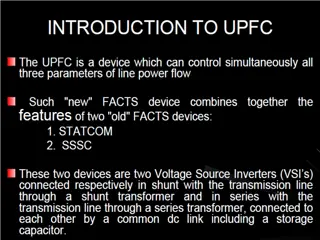
Reactive Power Reactive power is caused by reactive loads, i.e., inductance and capacitance Inductive current is lagging 90 behind the voltage Capacitive current is leading 90 before the voltage Examples of occurrence: DC-drives, electrical motors, some rectifier loads, uncompensated lighting With the 90 lag/lead, Q is always in a right angle to the active power. With Q going up or down depending on if it is inductive or capacitive P = active power (W) Q = reactive power (var) S = apparent power (VA) PF or cos( ) is the relation between P/Q/S 2 2025-04-17
Reactive Power Reactive power compensation is done by injecting an opposite reactive power to the grid. That way the amount of existing reactive power is reduced Inductive reactive power is compensated by capacitive reactive power Capacitive reactive power is compensated by inductive reactive power 3 2025-04-17
Reactive Power 4 2025-04-17
Reactive Power There are different power factors existing Displacement PF = DPF = PFdisp= cos( ) This is the PF between Active power (P) and Reactive power (Q) ??? = ?2+?2= ????????????? True Power Factor = PFTrue This is the PF between Active power (P), Reactive power (Q) as well as Distortion power (D) ??????= ?????? Power Factor has a similar problem as the THDI. The reference point can change over time. This can lead to a low PF only due to changes in the active loading A concept like the TDD does not exist for the power factor ? ? ? ? ?2+?2+?2= 5 2025-04-17
Reactive Power ? P (W) ???????= ???? 3 ? Q (var) ?????????= ???? 3 ? D (VA) ? ???????= ???? 3 ????? ???? 3 Sdisp(VA) ????????????= ?????? ???? 3 Stotal(VA) ????= This means, all the powers can be converted into currents 6 2025-04-17
Reactive Power A little bit math. It is actually everything nothing else than Pythagoras ?2+ ?2= ?2 ?????= ??????= ?2+ ?2 ?2+ ?2+ ?2 ???????2+ ?????????2+ ? ???????2= ????????????2+ ? ???????2 ????= What the ADF is doing when compensating: ????= (???????+ ??????????)2+(????????? ????)2+(? ??????? ? ???_????)2 7 2025-04-17
Reactive Power 8 2025-04-17