Practical Examples for 7-Segment Display Using VHDL
Explore practical examples on implementing a 7-segment LED display using VHDL. Learn how to display hexadecimal numbers, control individual segments, and utilize time multiplexing techniques. Take your VHDL skills to the next level with hands-on exercises and detailed explanations.

Download Presentation

Please find below an Image/Link to download the presentation.
The content on the website is provided AS IS for your information and personal use only. It may not be sold, licensed, or shared on other websites without obtaining consent from the author. If you encounter any issues during the download, it is possible that the publisher has removed the file from their server.
You are allowed to download the files provided on this website for personal or commercial use, subject to the condition that they are used lawfully. All files are the property of their respective owners.
The content on the website is provided AS IS for your information and personal use only. It may not be sold, licensed, or shared on other websites without obtaining consent from the author.
E N D
Presentation Transcript
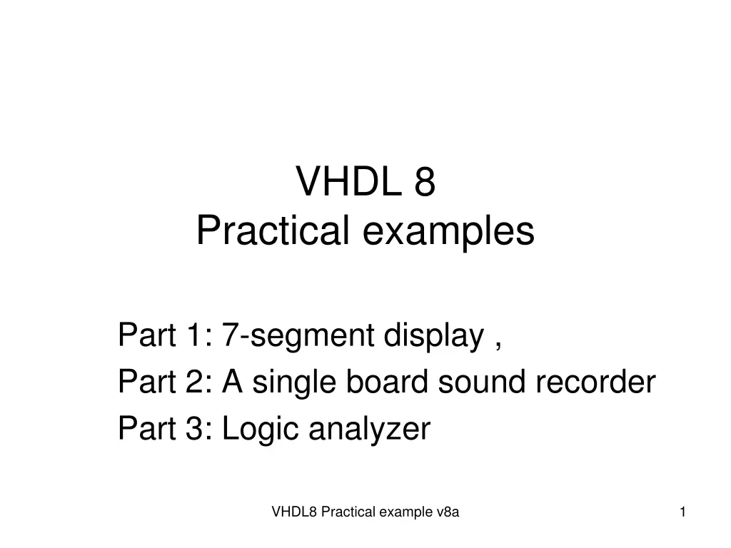
VHDL 8 Practical examples Part 1: 7-segment display , Part 2: A single board sound recorder Part 3: Logic analyzer VHDL8 Practical example v8a 1
Part 1 7-segment LED display using VHDL VHDL8 Practical example v8a 2
Lab5 In this exercise, you are required to display a hexadecimal number (XY) of two digits. Digit X on the left is to be controlled by input switch [3:0], and digit Y on the right is to be controlled by input switch [7:4]. To display the digits and save power, we have to switch between the two digitals using the digital selection signal (ssdcat) at a rate around 500kHz. Task1: Implement the above requirement to display the hexadecimal number XY. Task2: In addition to task1, add an input button to the system, after the button is pressed, the two digits will count from the number (XY) you entered to FF(hex) at a rate of one number per second. When the display reaches FF(hex), it will repeat counting from XY to FF again, and so on. Digits X Y https://www.beyond-circuits.com/wordpress/tutorial/tutorial4/ VHDL8 Practical example v8a 3
VHDL8 Practical example v8a Define these in entity port declaration entity sevenseg is Port ( clk : in STD_LOGIC; switch : in STD_LOGIC_VECTOR (7 downto 0); ssd : out STD_LOGIC_VECTOR (6 downto 0); ssdcat : out STD_LOGIC); end sevenseg; switch= user input switches led: zedboard LED control ssd: turn on/off individual LEDs in the active 7-segment ssdcat: selects which 7-segment is active 4
What is a 7-segment LED display? ssd :turn on/off individual LEDs in the active 7-segment ssd: turn on/off individual LEDs in the active 7- segment Input Value Segments Lit ssd: Output Value A B C D E F 0 1111110 B C 1 0110000 A B D E G 2 1101101 A B C D G 3 1111001 B C F G 4 0110011 A C D F G 5 1011011 A C D E F G 6 1011111 A B C 7 1110000 A B C D E F G 8 1111111 A B C F G 9 1110011 A B C E F G A 1110111 C D E F G b 0011111 A D E F C 1001110 B C D E G d 0111101 VHDL8 Practical example v8a A D E F G E 1001111 5 https://www.beyond-circuits.com/wordpress/tutorial/tutorial4/ A E F G F 1000111
Multiple 7-segment LED display method Time multiplexing: Because LED consumes high power Make one 7-segment active at one time will save power. Activate the 7-segment on the right then left at a rate of 1KHz and so on. ssdcat : selects which 7-segment is active VHDL8 Practical example v8a 6
VHDL for the 7-segment Input: clk (100MHz clock), digit(input code) process(clk) begin case digit is when "0000"=>ssd<="1111110"; when "0001"=>ssd<="0110000"; when "0010"=>ssd<="1101101"; when "0011"=>ssd<="1111001"; when "0100"=>ssd<="0110011"; when "0101"=>ssd<="1011011"; when "0110"=>ssd<="1011111"; when "0111"=>ssd<="1110000"; when "1000"=>ssd<="1111111"; when "1001"=>ssd<="1111011"; when "1010"=>ssd<="1110111"; when "1011"=>ssd<="0011111"; when "1100"=>ssd<="1001110"; when "1101"=>ssd<="0111101"; when "1110"=>ssd<="1001111"; when "1111"=>ssd<="1000111"; ssd: turn on/off individual LEDs in the active 7- segment end case; VHDL8 Practical example v8a 7
Create a 1KHz clock from a 100MHz clk ms_puls e (1KHz) 0.5ms If the clock frequency of clk is 100MHz Create a 1 KHz (or 1ms-period) clock: ms_pulse if rising_edge(clk) then if (count=99999) then ms_pulse <= not ms_pulse; count<=0; else count <= count + 1; end if; end if; 8 VHDL8 Practical example v8a
Select input switch switches depending on ms_pulse if ms_pulse='1' then digit <= switch(7 downto 4) else digit <= switch(3 downto 0); end if; ssdcat <= ms_pulse; ms_puls e (1KHz) 0.5ms VHDL8 Practical example v8a 9
library IEEE; --(Vivado ok) use IEEE.std_logic_1164.all; use IEEE.std_logic_arith.all; use IEEE.std_logic_unsigned.all; entity syn_counter is port ( CLK: in STD_LOGIC; RESET,CE, load, DIR: in STD_LOGIC; DIN: in std_logic_vector(3 downto 0); COUNT: inout std_logic_vector(3 downto 0)); end syn_counter; architecture Behavioral of syn_counter is begin process( reset, clk) begin if(reset = '1') then COUNT <= "0000"; else if(clk'event and clk = '1') then if(load = '1') then COUNT <= din; else if(ce = '1') then if( dir = '1') then count <= count + 1; else count <= count -1; end if; end if; end if; end if; end if; end process; end Behavioral; Example of a up/down counter (May be useful for the lab5 task2) 10 VHDL8 Practical example v8a
Hints for lab5-task2 Hints for Task2: To build the 1Hz, 8-bit counter with an output (call it sec_count), you need a slower input clock (1Hz). You can use the similar method for ms_pulse (1KHz) discussed earlier, and the input clock can be the ms_pulse signal. When the input button is pressed, toggle an enable signal (e.g. counter_en) to enable/disable the 1Hz counter . Also, initialize the counter value with the value of the switches. In each second, if the counter is enabled, increase the counter value by 1. If the counter value reaches 0xFF(hex), reset it to the value of the switches. Check the state of both sec_count and counter_en to determine the source of the digit to be displayed (either from the 1Hz counter or switches). VHDL8 Practical example v8a 11
More hints for lab5 task2 std_logic_vector cannot be incremented directly. Cast it to unsigned, signed or integer first. To convert signal type, you can refer to the figure in the appendix. For example, if you want to cast an integer sec_count to a 8-bit-unsigned std_logic_vector, you can type std_logic_vector(to_unsigned (sec_count, 8)) . Avoid updating the same signal or I/O in different processes or else you will encounter multiple driver error (Remember processes within the same architecture run concurrently). However, it is safe to read them in different processes. If you receive error message Poor placement for routing between an IO pin and BUFG while running implementation stage, you may add set_property CLOCK_DEDICATED_ROUTE FALSE [get_nets btn_IBUF] in the constraint file to omit the issue. VHDL8 Practical example v8a 12
Part 2 General concept of memory VHDL8 Practical example v8a 13
Basic structure of a microprocessor system CPU Memory Input/output and peripheral devices Glue logic circuits VHDL8 Practical example v8a 14
A computer system with a microprocessor Clock Oscillator Micro- Processor (CPU) memory Peripheral devices: serial, parallel interfaces; real-time-clock etc. Peripheral devices: serial, parallel interfaces; real-time-clock etc. VHDL8 Practical example v8a 15
Internal and external interfacing External interfacing Internal interfacing memory CPU Peripheral IO interface devices: such as USB bus, parallel bus, RS232 etc. Effectors: such as Motors, Heaters, speakers Keyboard mouse Peripheral devices: USB ports, Graphic card, real-time-clock etc. Light, Temperature sensors VHDL8 Practical example v8a 16
CPU, MCU are microprocessors CPU: Central Processing unit Requires memory and input/output system to become a computer (e.g. Pentium). MCU: micro-controller unit (or single chip computer) Contains memory, input output systems, can work independently (e.g. Arm7, 8051). Used in embedded systems such as mp3 players, mobile phones. VHDL8 Practical example v8a 17
Memory systems RAM/ROM VHDL8 Practical example v8a 18
Different kinds of Memory (RAM) Random access memory (RAM): data will disappear after power down. Static RAM (SRAM): each bit is a flip-flop Dynamic RAM (DRAM): each bit is a small capacitor, and is needed to be recharged regularly Since we only discuss static (SRAM) here, so the terms SRAM and RAM will be used interchangeably. VHDL8 Practical example v8a 19
Different kinds of Memory (ROM) Read only memory (ROM) UV-EPROM EEPROM FLASH ROM VHDL8 Practical example v8a 20
UV-EPROM VHDL8 Practical example v8a 21
Flash memory Or SD (secure digital card) http://videoengineer.net/images/sdc32g2.jpg VHDL8 Practical example v8a 22
Memory is like a tall building Address cannot change; content (data) can change Address content, e.g. A 32K-byte RAM 16-bit Address (H=Hex) 7FFF H 7FFF H 0ACD H 0001 H 0000 H 8-bit content (data) 35H 23H 24H 32H 2BH 23 VHDL8 Practical example v8a
How a computer works? 16-bit Address (H=Hex) 7FFF H 7FFF H 0ACD H 0001 H 0000 H 8-bit content (data) 35 23 24 32 2B (goto0ACD) Program is in memory CPU program counter (16 bit) [PC]: Keeps track of program location After power up PC=0000H VHDL8 Practical example v8a 24
A simple program in memory After power up, first instruction is in 0000H An example Address (H=Hex) instructions (Hex) 0AC3 25 0AC2 72 0AC1 3B 0AC0 24 0001 xx 0000 2B 8-bit machine code 8-bit content (data) Register A Instruction j+3 Instruction j+2 Instruction j+1 Instruction j Instruction 2 Instruction 1 25 VHDL8 Practical example v8a
Program to find 2+3=? Address (H=Hex) 8-bit content (data) Register A 0AC3 0AC2 0AC1 Send content of 0AC2 to output port (so this is the answer for 2+3 =5) Add 2 to Reg .A and save in next location Save 3 into Reg. A Goto address 0AC0 H 0AC0 0001 0000 26 VHDL8 Practical example v8a
CPU and Static memory (SRAM) interface Exercise: show the address space of the CPU and memory Data bus is bi-directional DIN,DOUT are using the same bus (D0-D7) VHDL8 Practical example v8a 27
Exercises 8.1 A) What is the address space for an address bus of 24 bits? B) How many address bits are required for a space of 4G bytes? C) Why do most computers use 8-bit as the bit length of an address? VHDL8 Practical example v8a 28
Memory read/write Timing diagrams http://www.alliancememory.com/pdf/AS6C62256.pdf VHDL8 Practical example v8a 29
A read cycle tRC, from SRAM memory to CPU Procedure: T0: setup address, T1: pull down /CE, T2: pull down /OE, T3: Dout data start to come out of memory, must be valid at T4 T4: Pull up /CE T5: pull up /OE For reading (minimum 55ns) All signals are coming out of CPU except Dout is from memory to CPU T0 T1 T2 T3 T4 T5 Note: T2 can happen at the same time as T1 but not before. T5 can happen at the same time as T4 but not before. 30 VHDL8 Practical example v8a
A write cycle tWC,, from CPU to SRAM memory Procedure: T0: setup address, T1: pull down /WE, T2: pull down /CE T3: Din data start to come out of CPU, must be valid at T4 T4: Pull up /CE and /OE at the same time For writing Data bus is bi-directional DIN,DOUT are using the same bus (D0-D7) Data bus is bi-directional DIN,DOUT are using the same bus (D0-D7) (minimum 55ns) All signals coming out of CPU Dout is at high impedance all the time T0 T1 T2 T3 T4 31 VHDL8 Practical example v8a
Exercises 8.2 (A): Redesign the CPU/SRAM interfaces circuit in figure 1 so that the address-range is 8000-FFFFH instead of 0000-7FFFH. VHDL8 Practical example v8a 32
Exercises 8.2B (B): Redesign the CPU/SRAM interface circuit in figure 1 to add another SRAM to make the system occupies the whole 0000-FFFFH address-range. VHDL8 Practical example v8a 33
How to read timing diagrams ? part1 Valid bus High-to-low, low-to-high uncertain regions VHDL8 Practical example v8a 34
How to read timing diagrams? part2 Float (High-Z) to uncertain then valid T0 T1 T2 VHDL8 Practical example v8a 35
Exercise8.3 , explain this timing diagram VHDL8 Practical example v8a 36
Address decoding VHDL8 Practical example v8a 37
Exercises 8.4 A CPU supports 128K-byte (has address pin A0-A16 = 17 pins, so 217=128K) of memory area. Exercise2.4: How many 32K-SRAMs do we need? VHDL8 Practical example v8a 38
Exercise 8.5a A CPU supports 128K-byte (has address pin A0-A16 = 17 pins, so 2^17=128K) of memory area. We need an address decoder to enable the (/CS) input of each SRAM. Complete the following diagram. Address decoder /CS0 A0,A1 /CS1 /CS2 /CS3 Address lines: A15, A16 32K SRAM1 /CS A0-A14 /OE /RD 32K SRAM2 /CS A0-A14 /OE /RD 32K SRAM3 /CS A0-A14 /OE /RD 32K SRAM4 /CS A0-A14 /OE /RD A0-A14 /WR /RD Data bus D0-D7 D0-D7 D0-D7 D0-D7 D0-D7 VHDL8 Practical example v8a 39
Exercise 8.5b :Memory decode for a system with 128K-byte size using four 32-byte RAM chips , fill in the blanks. A16,A15, ..A0 (17 bits) Address range ( 5 hex.) Range size 32K 0 0xxx xxxx xxxx xxxx 0 0000 - 0 7FFF H 32K 0 1xxx xxxx xxxx xxxx 0 8000 - 0 FFFFH __ K _ _xxx xxxx xxxx xxxx 1 0000 - 1 7FFFH _ ____ - _ ____H 32K 1 1xxx xxxx xxxx xxxx VHDL8 Practical example v8a 40
Exercise 8.5c: fill in the address decoder truth table A16 ,A15 /CS0 0 0 /CS1 /CS2 /CS3 0 1 1 0 1 1 VHDL8 Practical example v8a 41
Address decode rules Decode the upper address lines using a decoder. Connect lower address lines directly to memory devices. VHDL8 Practical example v8a 42
Exercise 8.6 Fill in the modes (in, out, inout or buffer) of the input/output signal. SRAM (memory) CPU address lines (A0- A16) data lines (D0-D7) /CS,/OE and /WE lines VHDL8 Practical example v8a 43
Exercise 8.7 tRC Referring to the figure, what would happen if /RD of the CPU (connected to /OE) goes up before the data valid region occurs? ADD /CE Or (/CS) /OE DOUT VHDL8 Practical example v8a 44
Exercise 8.8 : Referring to the Figure, if tAS=0ns, twc=100ns,tCW= 80ns, give comments on the limits of tAW, tWPand tDW.. tWC ADD tCW /CE Or (/CS) tAW tWP /WE tDW DIN VHDL8 Practical example v8a 45
Part 3 The Logic Analyzer VHDL8 Practical example v8a 46
The Logic Analyzer Overall diagram Serial port DA_in[7..0] Reset Rec Play Xilinx based hardware ARM7 board DA_out[7..0] Display waveform RAM VHDL8 Practical example v8a 47
Memory (32K) interface entity logic_rec is Port ( clk40k_in: in std_logic; reset: in std_logic; rec, play: in std_logic; --user inputs -- mem RAM bus bar_ram_we27: out std_logic; bar_ram_cs20: out std_logic; bar_ram_oe22: out std_logic; -- 32k-byte ram_address_buf: buffer std_logic_vector(14 downto 0); ram_data_inout: inout std_logic_vector(7 downto 0); da_data_out: buffer std_logic_vector(7 downto 0); da_data_in: in std_logic_vector(7 downto 0)); end logic_rec; VHDL8 Practical example v8a 48
Static memory (SRAM 32Kbytes) data pins Diagrams are obtained from data sheet of HM62256B VHDL8 Practical example v8a 49
HM62256B Memory read timing diagrams VHDL8 Practical example v8a 50


")


")
")


 interface")


 interface")
")
