Preliminary Application of Hardware-in-the-Loop Simulation Technology in Fusion Research
Explore how Hardware-in-the-Loop (HIL) simulation technology can enhance control systems in Fusion Research, saving time and costs while ensuring safety. This research delves into the implementation, performance testing, and future implications of HIL simulation in fusion experiments at ASIPP EAST.
Download Presentation

Please find below an Image/Link to download the presentation.
The content on the website is provided AS IS for your information and personal use only. It may not be sold, licensed, or shared on other websites without obtaining consent from the author. If you encounter any issues during the download, it is possible that the publisher has removed the file from their server.
You are allowed to download the files provided on this website for personal or commercial use, subject to the condition that they are used lawfully. All files are the property of their respective owners.
The content on the website is provided AS IS for your information and personal use only. It may not be sold, licensed, or shared on other websites without obtaining consent from the author.
E N D
Presentation Transcript
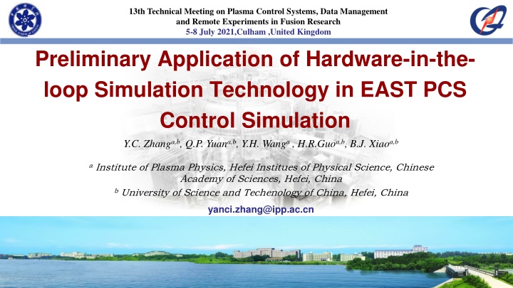
13th Technical Meeting on Plasma Control Systems, Data Management and Remote Experiments in Fusion Research 5-8 July 2021,Culham ,United Kingdom Preliminary Application of Hardware-in-the- loop Simulation Technology in EAST PCS Control Simulation Y.C. Zhanga,b, Q.P. Yuana,b, Y.H. Wanga, H.R.Guoa,b, B.J. Xiaoa,b a Institute of Plasma Physics, Hefei Institues of Physical Science, Chinese Academy of Sciences, Hefei, China b University of Science and Techenology of China, Hefei, China yanci.zhang@ipp.ac.cn ASIPP EAST
Content Content Background of this research Introduction of HIL simulation Simulation environment comparison Implement HIL framework Model design and data interface design Perfomance test Model solving perfomance Reflective memory card performance HIL test ( Closed loop ) Conclusion and Future works ASIPP EAST 2
Background Background Introduction of HIL Hardware-in-the-Loop (HIL) simulation is a technique that can replace the physical part of a machine or system with the digital model. Benefits Enhance Quality Reduce Cost Increase Safety With HIL simulation, time and money can be saved during the developing of control system With HIL simulation, the HIL simulation can be correct action of a control deeply embedded in system to various failure the design process by modes can effectively be test automation. tested. ASIPP EAST 3
Background Comparison Model-in-the-loop simulation does not reflect the behavior of the control algorithm under the real condition , as well as the behavior of the real hardware. ASIPP EAST 4
Implement Framework of the HIL Simulation Testing object Implement ASIPP EAST 5
Implement Model to be built Control model Model design Plant model Controller model (MIL) Plant model Rigid plasma model Coil current model PCS (HIL) Data interface Control logic of the EAST RZIP algorithm Q.P. Yuan, B.J. Xiao, Z.P. Luo et al 2013 Nucl. Fusion ASIPP EAST 6
Implement Data interface design and real-time task deploy Development of reflective memory card driver based on labview The signal setting and monitoring GUI of the VeriStand DMA driver and performance monitoring Pass data to VeriStand Engine through custom device loop Deploy real-time tasks with VeriStand Model execution deployment Design the simulation process, Deploy data to the channel Run the model in real time Workspace deployment Data logging Test start control Real-time monitoring data Design data interface in PCS ASIPP EAST 7
Performance test Model Solving Perfomance Uncontrollable model evolution PCS minimum control cycle May need to reserve time for data processing 100us 85us Suitable interval Lower computer Engine's mechanism for processing real-time models Model solution time (per step) ASIPP EAST 8
Performance test Model Solving Perfomance The dimensions and purpose of the test The solution speed of the model not only depends on the hardware performance of the lower computer and the operating system, but also depends on the selection of the solver algorithm (ode1(Euler),ode3(Bogacki-Shampine)) A matrix order 104 x 104 Ode1 (per step) 27us Ode3 (per step) 75us Matlab 73 X 73 18us 50us Ip Z R 12 x 12 6us 12us Linux-rt PCL=10kHz The result of running the controller model and plasma rigidity model with the order of 104X104, ode3 ASIPP EAST 9
Performance test Reflective memory card performance Verify the DMA read and write capabilities of the reflective memory card in the lower computer PCL = 5000hz , Calculate the average of time every 1000 points. Number of Number of channels channels PXI18::15::INSTR PXI18::15::INSTR (read) (read) PXI18::15::INSTR PXI18::15::INSTR (write) (write) PXI18::12::INSTR PXI18::12::INSTR (read) (read) PXI18::15::INSTR PXI18::15::INSTR (write) (write) 1 57.9 64 60 66.5 13 58.7 65.5 62.2 65.4 100 65.3 74 71 75.6 In this system, we use two reflective memory cards to read and write separately. ASIPP EAST 10
Performance test HIL test ( Closed loop ) Test Case : Connect the PCS to the lower computer for data in real-time, and the lower computer deploys the coil current model Verification object HIL PS1 PS1 MIL Compare the real-time running result of PCS with the running result of the model in matlab to verify the execution result of PCS. Pf1 Pf1 By comparing the results, we can know the agreement between the behavior of the controller model we built and the actual PCS . ASIPP EAST 13
Conclusion Conclusion Conclusion and Future works Conclusion: It has been confirmed that some preliminary hardware-in-the-loop simulation can be implemented in PCS control simulations . The hardware-in-the-loop simulation can efficiently test the PCS and verify the behavior of the PCS under real working conditions. Future works: Consider testing more PCS modules. Consider using a data-driven model to realize hardware-in-the-loop simulation and design a model that is more suitable for a fixed-step solver. ASIPP EAST 12


