Explore NIST's measurement capabilities at 83 GHz using mm-wave channel sounders for the IEEE 802.11ay task group's channel modeling needs. The presentation showcases the advanced features of the 28/83 GHz channel sounder and the precise measurement setup for multidimensional power profiles.
Please find below an Image/Link to download the presentation.
The content on the website is provided AS IS for your information and personal use only. It may not be sold, licensed, or shared on other websites without obtaining consent from the author. If you encounter any issues during the download, it is possible that the publisher has removed the file from their server.
You are allowed to download the files provided on this website for personal or commercial use, subject to the condition that they are used lawfully. All files are the property of their respective owners.
The content on the website is provided AS IS for your information and personal use only. It may not be sold, licensed, or shared on other websites without obtaining consent from the author.
E N D
Presentation Transcript
doc.: IEEE 802.11-14/xxxxr0 doc.: IEEE 802.11-15/0840-01-00ay July 2015 NIST Preliminary Channel Measurements at 83 GHz Date: 2015-07-14 Authors: Name Peter Papazian Kate Remley Camillo Gentile Nada Golmie Jelena Senic Jian Wang Jae-Kark Choi Affiliations NIST NIST NIST NIST NIST NIST NIST Address Boulder, CO Boulder, CO Gaithersburg, MD Gaithersburg, MD Boulder, CO Gaithersburg, MD Gaithersburg, MD Phone (303) 497-7078 (303) 497-3652 (301) 975-3685 (301) 975-4190 (303) 497-6166 (301) 975-8012 (301) 975-6049 email peter.papazian@nist.gov kate.remley@nist.gov camillo.gentile@nist.gov nada.golmie@nist.gov jelena.senic@nist.gov jian.wang@nist.gov jae-kark.choi@nist.gov Submission Slide 1 Camillo Gentile, NIST
doc.: IEEE 802.11-14/xxxxr0 doc.: IEEE 802.11-15/0840-01-00ay July 2015 Abstract We have conducted a number of measurement campaigns 83 GHz using NIST mm-wave channel sounders. The purpose of this presentation is to show the measurement capabilities we can provide to task group IEEE 802.11ay for channel modelling. Submission Slide 2 Camillo Gentile, NIST
doc.: IEEE 802.11-14/xxxxr0 doc.: IEEE 802.11-15/0840-01-00ay July 2015 28 / 83 GHz Channel Sounder Characteristics 1TX antenna Omni-directional in azimuth 45 beamwidth in elevation 16-antenna RX array 8 elements every 45 in azimuth at 0 elevation (no cap) 8 elements every 45 in azimuth at 45 elevation (black cap) Can extract double-directional angle-of-arrival Each horn antenna has 45 beamwidth 2 GHz null-to-null bandwidth Robot-guided navigational system Can collect hundreds of GB of data in just minutes Can support use cases with high mobility Complete channel measurement sweep in 65 s Untethered synchronization through rubidium clocks RX array Submission Slide 3 Camillo Gentile, NIST
doc.: IEEE 802.11-14/xxxxr0 doc.: IEEE 802.11-15/0840-01-00ay July 2015 Measurement Setup Wall ( , ) Ground-truth azimuth and elevation angle-of-arrival of direct path are known Since TX and RX at same height, elevation angle is always 0 Ground-truth robot velocity is known Submission Slide 4 Camillo Gentile, NIST
doc.: IEEE 802.11-14/xxxxr0 doc.: IEEE 802.11-15/0840-01-00ay July 2015 Multidimensional Power Profiles ? ?,? = ? ,? = ? ? ? ?,?,? = ? ? Previously, angle resolution corresponded to discrete angular spacing of antenna elements Average angle error was 22.5 Now through conventional beamforming, impulse response at center of array can be generated ? ?,?,? Testing shows average error in azimuth angle is now 4 Forthcoming: double-directional antenna / phase calibration between TX-RX Reduce angle error further through super-resolution techniques Submission Slide 5 Camillo Gentile, NIST
doc.: IEEE 802.11-14/xxxxr0 doc.: IEEE 802.11-15/0840-01-00ay July 2015 Path Loss Path-loss exponent of transmitter-facing antenna is computed as 2.0 Discrepancy from free-space loss is because antenna patterns not yet deconvolved from measurements Path-loss exponent of opposite-facing antenna is about -0.25 As the robot moves towards wall, position-dependent reflections from wall observed In conference room, distance up to 12 m Submission Slide 6 Camillo Gentile, NIST
doc.: IEEE 802.11-14/xxxxr0 doc.: IEEE 802.11-15/0840-01-00ay July 2015 RMS Delay Spread Transmitter-facing antennas (0 and 45 off-axis azimuth) at elevation 0 experience the smallest delay spreads because they contain the most dominant paths Transmitter-facing antennas at elevation 45 have slightly longer delays per antenna compared to elevation 0 because the dominant paths are relatively weaker Opposite-facing antennas (135 , 180 off-axis azimuth) experience the second shortest delay spreads because they have strong reflections from walls The side-facing antennas (90 off-axis azimuth) experience the longest delay spreads because they have the weakest dominant paths Submission Slide 7 Camillo Gentile, NIST
doc.: IEEE 802.11-14/xxxxr0 doc.: IEEE 802.11-15/0840-01-00ay July 2015 Small-scale Fading: Measurements Antennas with 0 elevation Antennas with 45 elevation Antennas with 0 elevation pick up stronger paths (Ch13 picks up direct path) Rician K-factor of antennas with stronger paths much larger Ch12 has same azimuth angle as Ch13, but has 45 elevation Submission Slide 8 Camillo Gentile, NIST
doc.: IEEE 802.11-14/xxxxr0 doc.: IEEE 802.11-15/0840-01-00ay July 2015 Small-scale Fading: Statistics 1 1 1 0.9 0.9 0.9 Empirical CDF Rayleigh CDF Empirical CDF Rician CDF Empirical CDF TWDP CDF 0.8 0.8 0.8 0.7 0.7 0.7 0.6 0.6 0.6 F(x) F(x) F(x) 0.5 0.5 0.5 0.4 0.4 0.4 0.3 0.3 0.3 0.2 0.2 0.2 0.1 0.1 0.1 0 0 0 0.5 1 1.5 2 2.5 x 3 3.5 4 4.5 -3 0.2 0.4 0.6 0.8 1 1.2 1.4 1.6 1.8 2 0.5 1 1.5 2 x 2.5 3 3.5 -3 x -3 x 10 x 10 x 10 13% TWDP 4% Rayleigh 83% Rician For one location, each of the 16 antennas considered separately For each antenna, the delay profile was divided into 1-ns bins The amplitude of each bin over 128 time snapshots was fit to a distribution KS-test with 95% confidence used to determine best fit Example distributions shown above Submission Slide 9 Camillo Gentile, NIST
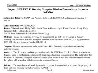
doc.: IEEE 802.11-14/xxxxr0 doc.: IEEE 802.11-15/0840-01-00ay July 2015 Doppler Frequency Spectrum 4.5 Direct path Reflected path WALL 4 3.5 3 2.5 |Hp( , f)| RX 2 1.5 1 TX 0.5 0 -800 -600 -400 -200 0 200 400 600 800 Doppler frequency shift, f (Hz) Direct and reflected paths only All paths Example Doppler spectrum at a single location Direct and reflected paths have opposite Doppler shifts Other paths have Doppler shifts in between the direct and reflected, but less dominant Coherence time computed from the inverse of the RMS spread Submission Slide 10 Camillo Gentile, NIST
doc.: IEEE 802.11-14/xxxxr0 doc.: IEEE 802.11-15/0840-01-00ay July 2015 Doppler Frequency Shift: Estimated vs. Ground-truth Direct path (estimated) Reflected path (estimated) Direct path (ground-truth) 300 WALL 200 Doppler frequency shift, f (Hz) 100 RX 0 -100 TX -200 -300 0 10 20 30 40 50 60 Robot position index Ground truth Doppler shift estimated from known robot velocity: ?? =? ? ?? Estimated Doppler shift of direct path tracks ground-truth value very closely Direct path and wall-reflected paths have opposite Doppler shifts Submission Slide 11 Camillo Gentile, NIST
doc.: IEEE 802.11-14/xxxxr0 doc.: IEEE 802.11-15/0840-01-00ay July 2015 Upcoming Work Measurements in other areas at 83 GHz Conference room (complete) Living room Server room Stadium 60 GHz channel sounder should be ready for measurements in October 2015 Has 8 elements at TX and 16 elements at RX Will likely have 4 GHz null-to-null bandwidth Submission Slide 12 Camillo Gentile, NIST