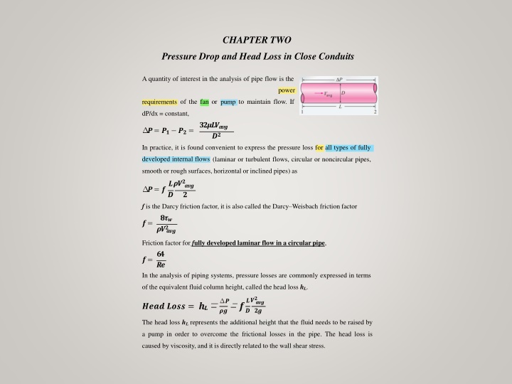
Pressure Drop and Head Loss in Pipe Flow Analysis
Explore the concepts of pressure drop, head loss, pumping power requirements, and flow analysis in piping systems through this comprehensive guide. Learn about friction factors, equivalent fluid column height, energy equations, and practical examples. Discover how viscosity, wall shear stress, and various factors influence pressure loss in pipes.
Download Presentation

Please find below an Image/Link to download the presentation.
The content on the website is provided AS IS for your information and personal use only. It may not be sold, licensed, or shared on other websites without obtaining consent from the author. If you encounter any issues during the download, it is possible that the publisher has removed the file from their server.
You are allowed to download the files provided on this website for personal or commercial use, subject to the condition that they are used lawfully. All files are the property of their respective owners.
The content on the website is provided AS IS for your information and personal use only. It may not be sold, licensed, or shared on other websites without obtaining consent from the author.
E N D
Presentation Transcript
CHAPTER TWO Pressure Drop and Head Loss in Close Conduits A quantity of interest in the analysis of pipe flow is the power of the fan or to maintain flow. If requirements pump dP/dx = constant, ???????? ?? ?= ?? ??= In practice, it is found convenient to express the pressure loss for all types of fully developed internal flows (laminar or turbulent flows, circular or noncircular pipes, smooth or rough surfaces, horizontal or inclined pipes) as ???? ??? ?= ?? f is the Darcy friction factor, it is also called the Darcy Weisbach friction factor ? ??? ??? ?= ??? Friction factor for fully developed laminar flow in a circularpipe, ?? ?? In the analysis of piping systems, pressure losses are commonly expressed in terms ?= of the equivalent fluid column height, called the head loss hL. ??? ? ?? ??? ? ? ?? The head loss hLrepresents the additional height that the fluid needs to be raised by a pump in order to overcome the frictional losses in the pipe. The head loss is caused by viscosity, and it is directlyrelated to the wall shear stress.
major loss and denoted hLmajorand the head minor loss and denoted hLminor, and effects in the straight pipes, termed the loss in the various pipe components, termed the hL= hL,major + hL,minor Once the pressure loss (or head loss) is known, the required pumping power to overcome the pressure loss is determined from ? ????,?= ? ??= ?????= ? ??? The average velocity for laminar flow in a horizontal pipe is, ? ?? ???? ????= Then the volume flow rate for laminar flow through a horizontal pipe of diameter D and length L becomes ? = ? ? ? = ? ??? ??? or ??? ? ? = ? ??? ????? Energy equation for steady, incompressible one-dimensional flow in terms of heads ?? ?? + ?+??+?????= ?? ?? ?? ?? + ?+??+?? ? ? ? ? ? ?+?? ?? ?? For inclined pipes ( ? ???????) ?? ???? ? =( ? ???????) ??? ????? ????= Note: Uphill flow: >0 and sin >0, Downhill flow: <0 and sin <0
Ex2-1: Consider the flow of oil, v=0.0026m2/s, 40cm diameter pipeline with average velocity of 0.5 m/s. A 300 m long section of the pipeline passes through the icy waters of a lake. Disregarding entrance effects, find the pumping power required to overcome the pressure losses and to maintain the flow of oil in the pipe =0.8 kg/m s) is flowing steadily through a 5cm Ex2-2: Oil at 20 C ( =888 kg/m3and diameter 40m long pipe. The pressure at the pipe inlet and outlet are measured to be 745 and 97 kPa, respectively. Determine the flow rate of oil through the pipe assuming the pipe is (a) horizontal, (b) inclined 15 upward, (c) inclined 15 downward. Also verify that the flow through the pipe is laminar. Ex2-3: Oil ( =900 kg/m3& =0.4 N.s/m2) flows in a 2cm pipe of diameter. FIND (a) What pressure drop p, is needed to produce a flow rate of 2 10-5m3/s; if the pipe is horizontal with x1= 0 and x2=10 m? (b) How steep a hill, , must the pipe be on if the oil is to flow through the pipe at the same rate as in part (a), but with p1=p2 Ex2-4: SAE 30 ( =891 kg/m3& =0.4 N.s/m2) oil at 20 C flows in the 3-cm-diameter pipe, which slopes at 37 . For the pressure measurements shown, determine (a) whether the flow is up or down and (b) Flow rate in m3/h.
The pressure drop P for steady incompressible turbulent flow in a circular pipe of 13 Pressure Loss in Turbulent flows diameter D can be written in functional form as P=F f (V, D, L, , , ) Where V is the average velocity, L is the pipe length, and is a measure of the roughness of the pipe wall. The dependence of P on the fluid properties and is expected because of the dependence of on these parameters. friction factor in fully developed turbulent pipe flow depends on the Reynolds The number of the mean height of and the relative roughness /D, which is the ratio roughness of the pipe to the pipe diameter. The functional form of this dependence can t be obtained from a theoretical analysis, and all available results are obtained from using artificially roughened surfaces. painstaking experiments The friction factor was calculated from the measurements of the flow rate and the pressure drop. The experimental results obtained are presented in tabular, graphical, and functional forms obtained by curve-fitting experimental data. For transition and turbulent flow in smooth as well as rough pipes, the following implicit relation known as the Colebrook equation: ?/? ?.? ?.?? ?? ? ? = ?.? ? ? ?( + ) ?
The Moody chart presents the friction factor for pipe flow as a function of the 14 Reynolds number and /D over a wide range. It is developed for circular pipes, and noncircular pipes by replacing the diameter by the hydraulic diameter. Commercially available pipes differ from those used in the experiments in that the roughness of pipes in the market is not uniform and it is difficult to give a precise description of it. Equivalent roughness values for some commercial pipes are given in shown Table as well as on the Moody chart. But it should be kept in mind that may increase these values are for new pipes, and the relative roughness of pipes as a result of with use the friction factor may increase by a factor of 5 to 10. The Colebrook equation is corrosion, scale buildup, and precipitation. As a result, implicit in f, and thus the determination of the friction factor requires some iteration unless an equation solver. An approximate explicit relation for f was given by S. E. Haaland in 1983 as ?.?? ?.? ?? ?/? ?.? ? ?.?? ? ?[ +( ) ] ? The results obtained from this relation are within 2 percent of those obtained from the Colebrook equation.
Types of Fluid Flow Problems 15 In the design and analysis of piping systems that involve the use of the Moody chart (or the Colebrook equation), we usually encounter three types of problems (the fluid and the roughness of the pipe are assumed to be specified in all cases) 1. Determining the pressure drop (or head loss) when the pipe length and diameter are given for a specified flow rate (or velocity) 2. Determining the flow rate when the pipe length and diameter are given for a specified pressure drop (or head loss) 3. Determining the pipe diameter when the pipe length and flow rate are given for a specified pressure drop (or head loss) Problems of the first type are straightforward and can be solved directly by using the Moody chart. Problems of the second type and third type are commonly encountered in engineering design (in the selection of pipe diameter, for example, that minimizes the sum of the construction and pumping costs), but the use of the Moody chart with such problems requires an iterative approach unless an equation solveris used. To avoid tedious iterations in head loss, flow rate, and diameter calculations, Swamee and Jain proposed the following explicit relations in 1976 that are accurate to within 2 percent of the Moody chart: Q Q Q Q Q
Ex2-5: Water at 20C (= 998 kg/m3and =1.00210-3) is flowing steadily in a 5 16 cm diameter horizontal pipe made of stainless steel at a rate of 0.006 m3/s. Determine the pressure drop, the head loss, and the required pumping power input for flow over a 60 m long section of the pipe. Ex2-6: Kerosene at 20 C is pumped at 0.15 m3/s through 20 km of 16-cm-diameter castiron horizontal pipe. Compute the input power in kW required if the pumps are 85 percent efficient. Ex2-7: Water at 15 C ( =999.1 kg/m3and =1.138 10-3kg/m s) is flowing steadily in a 30 m long and 4 cm diameter horizontal pipe made of stainless steel at a rate of 8 L/s Determine (a) the pressure drop, (b) the head loss, and (c) the pumping power requirement to overcome this pressure drop. Ex2-8: Consider an air solar collector that is 1m wide, 5m long and has a constant spacing of 3cm between the glass cover and the collector plate. Air flows at an average temperature of 45 C at a rate of 0.15m3/s through the 1m wide edge of the collector along the 5m long passageway. Disregarding the entrance and roughness effects, determine the pressure drop in the collector. Ex2-9: Heated air at 1atm and 35oC is to be transported in a 150-m-long circular plastic duct at a rate of 0.35m3/s. If the head loss in the pipe is not to exceed 20 m, determine the minimum diameter of the duct. Ex2-10: Gasoline at a rate of (0.1m3/s) is being discharged from a pipe at point 2 at elevation 66.66m. Point 1 is located 965.5 m along the pipe from point 2, is at elevation 82.65, and pressure there is 2.5 kPa. If the pipe roughness is 0.5 mm, what pipe diameter is needed for discharge gasoline. Assume the flow velocity is constant in each point (y=7.05kN/m3, =2.92 10-4N.s/m2, p=719kg/m3)
Ex2-11: The head loss per kilometer of 20 cm asphalted cast-iron pipe is 12.2 m. 17 What is the flow rate of water through the pipe? Ex2-12: Water (T=20 C) flows from a tank through a 50 cm diameter steel pipe. Determine the discharge of water MINOR LOSSES The fluid in a typical piping system passes through various fittings, valves, bends, elbows, tees, inlets, exits, enlargements, and contractions in addition to the pipes. These components interrupt the smooth flow of the fluid and cause additional losses because of the flow separation and mixing they induce. In a typical system with long pipes, these losses are minor compared to the total head loss in the pipes (the major losses) and are called minor losses. In some cases the minor losses may be greater than the major losses. This is the case, for example, in systems with several turns and valves in a short distance. The head loss introduced by a completely open valve, for example, may be negligible. But a partially closed valve may cause the largest head loss in the system. Minor losses are usually expressed in terms of the loss coefficient KL(also called the resistance coefficient), defined as ?? ? = ??/(??) ? The total head loss in a piping system is determined from hL,total= hL,major+ hL,minor ? ?? ?? + ? ? ?


