Explore microinstruction and microoperations in computer architecture, focusing on the Basic Computer. Understand the format, fields, and examples of microoperations for efficient programming.
Please find below an Image/Link to download the presentation.
The content on the website is provided AS IS for your information and personal use only. It may not be sold, licensed, or shared on other websites without obtaining consent from the author. If you encounter any issues during the download, it is possible that the publisher has removed the file from their server.
You are allowed to download the files provided on this website for personal or commercial use, subject to the condition that they are used lawfully. All files are the property of their respective owners.
The content on the website is provided AS IS for your information and personal use only. It may not be sold, licensed, or shared on other websites without obtaining consent from the author.
E N D
Presentation Transcript
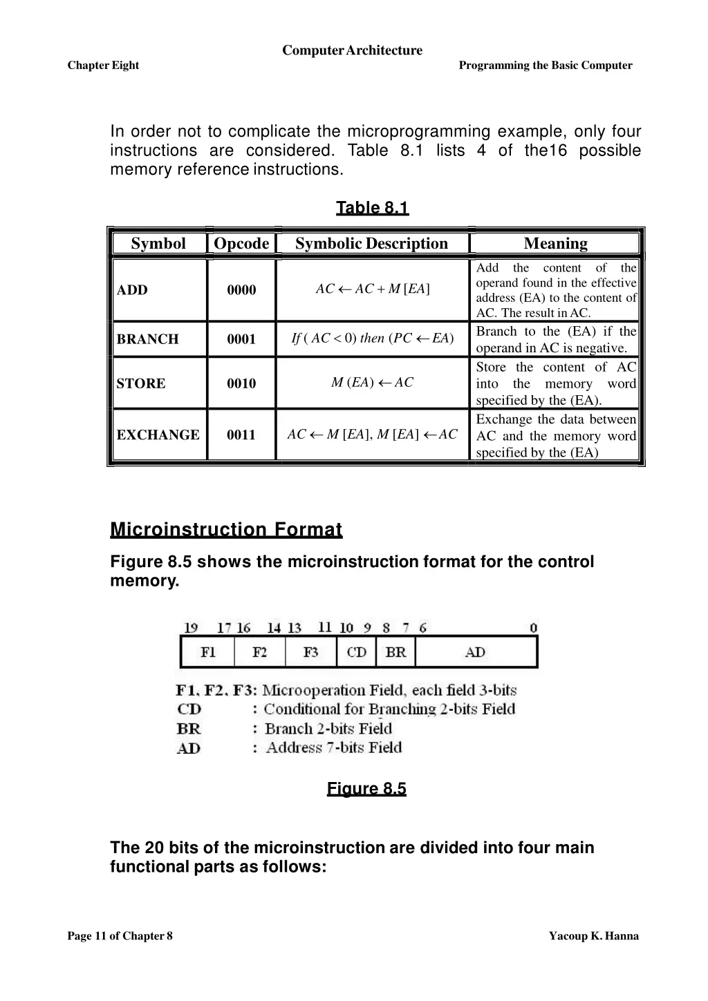
ComputerArchitecture ChapterEight Programming the Basic Computer In order not to complicate the microprogramming example, only four instructions are considered. Table 8.1 lists 4 of the16 possible memory reference instructions. Table 8.1 Symbol Opcode Symbolic Description Meaning Add operand found in the effective address (EA) to the content of AC. The result inAC. Branch to the (EA) if the operand in AC is negative. Store the content of AC into the memory specified by the (EA). Exchange the data between AC and the memory word specified by the (EA) the content of the AC AC + M[EA] ADD 0000 If ( AC 0) then (PC EA) BRANCH 0001 M (EA) AC STORE 0010 word AC M [EA], M [EA] AC EXCHANGE 0011 Microinstruction Format Figure 8.5 shows the microinstruction format for the control memory. Figure 8.5 The 20 bits of the microinstruction are divided into four main functional parts as follows: Page 11 of Chapter8 Yacoup K.Hanna
ComputerArchitecture Chapter Eight Programming the Basic Computer 1. The Microoperation Fields (F1, F2, andF3) The Microoperation field is subdivided into three subfields (F1, F2, and F3) of three bits each. The three bits in each field are encoded to specify seven distinct microoperations microoperation (i.e. no operation) as listed in Table 8.2. This gives a total of 21 microoperations. Therefore; microoperations can be chosen for a microinstruction, one from each field. If for example; fewer than three microoperations are needed for a given microinstruction, one or more of the fields will use the binary code 000 (i.e. no operation). plus one idle No more than three Table 8.2 Microoperationfields F1 F2 000 001 010 011 100 101 110 111 Microoperation Symbol F3 None AC AC + DR AC 0 AC AC + 1 AC DR AR DR(0-10) AR PC M [AR] DR NOP ADD CLRAC INCAC DRTAC DRTAR PCTAR WRITE 000 001 010 011 100 101 110 111 None AC AC - DR AC AC DR AC AC DR DR M [AR] DR AC DR DR + 1 DR (0-10) PC NOP SUB OR AND READ ACTDR INCDR PCTDR 000 001 010 011 100 101 110 111 None AC AC DR AC AC AC shl AC AC shr AC PC PC + 1 PC AR Rserved NOP XOR COM SHL SHR INCPC ARTPC Page 12 of Chapter8 Yacoup K.Hanna
ComputerArchitecture ChapterEight Programming the Basic Computer Example Suppose that a given microinstruction specify two simultaneous microoperations from F2 and F3 and none from Fl. DR M[AR] PC PC + 1 with F2 = 100 with F3 =101 And The nine bits of the Microoperation fields will then be 000 100 101. All transfer-type microoperations symbols use five letters: a. The first two letters designate the source register. b. The third letter is always a T. c. The last two letters designate the destination register. Example a. The microoperation that specifies the transfer PC AR the symbol ARTPC, which stands for a transfer from AR to PC. has b. The microoperation that specifies the transfer DR AC the symbol ACTDR, which stands for a transfer from AC to DR. has 2. The Condition for Branching Field(CD) This microinstruction field selects status bit conditions. It consists of two bits which are encoded to specify four status bit conditions as listed in Table 8.3. Table 8.3 CD Condition Symbol Comments Unconditional Branch Indirect Address Bit Sign Bit of AC Zero value in AC 00 01 10 11 Always =1 DR(15) AC(15) AC = 0 U I S Z Notes a. The first condition is always a 1, so that a reference to CD = 00 will always find the condition to be true. When this condition is used in conjunction with the BR (branch) field, it provides an unconditional branch operation. b. The symbols U, I, S, and Z will be used for the four status bits for writing microprograms in symbolic form. Page 13 of Chapter8 Yacoup K.Hanna
ComputerArchitecture ChapterEight Programming the Basic Computer 3. The Branch Field (BR) The BR field which consists of two bits specifies the type of branch to be used (see table 8.4). This field is used in conjunction with the address field AD to choose microinstruction. Table 8.4 the address of the next BR Symbol 00 JMP Function CAR AD if condition = 1 CAR CAR + 1 if condition =0 CAR AD, SBR CAR + 1 if condition= 1 CAR CAR + 1 if condition =0 CAR SBR (Return from subroutine) CAR(2-5) DR(11-14), CAR(0,1,6) 0 01 CALL 10 11 RET MAP Table 8.4 shows: - a. When BR = 00, the control performs a jump (JUMP) operation. Depending on the value of the CD field. When the status bit condition specified in the CD field is equal to 1, the next address in the AD field is transferred to the control address register CAR. Otherwise, CAR isincremented. b. When BR = 01, it performs a call to subroutine (CALL) operation. Depending on the value of the CD field. When the status bit condition specified in the CD field is equal to 1, the next address in the AD field is transferred to the control address register CAR. Otherwise, CAR isincremented. Note. The JUMP & CALL operations are identical except that a CALL microoperation stores the return address in the subroutine register SBR. c. When BR = 10, the return from subroutine is accomplished. This causes the transfer of the return address from SBR to CAR. Page 14 of Chapter8 Yacoup K.Hanna
ComputerArchitecture ChapterEight Programming the Basic Computer d. When BR = 11, the mapping from the operation code bits of the instruction to an address for CAR is accomplished. This mapping is as depicted in figure 8.3. The bits of the operation code are in DR (11-14) after an instruction is read from memory. Note. It is clear from the table 8.4 that the last two conditions in the BR field are independent of the values in the CD and AD fields. 4. The Address Field (AD) The AD field contains a branch address. The address field is seven bits wide, since the control memory has 128 = 27words. Symbolic Microinstructions The symbols defined in tables 8.2, 8.3, and 8.4 could be used to specify microinstructions in symbolicform. The simplest microprogram microinstruction and to give users the capability for defining their own symbolic address. way to formulate an assembly language for a is to define symbols for each field of the Each symbolic microinstruction is divided into five fields: 1. The Label Field This field may be left empty or it may specify a symbolic address. A label is terminated with a colon (:). 2. The Microoperations Field (F1, F2, andF3) This field consists of one, two, or three symbols, separated by commas, from those defined in table 8.2. There may be no more than one symbol from eachfield. The NOP symbol is used when the microinstruction has no microoperations, this will be translated by the assembler to nine zero's. Page 15 of Chapter8 Yacoup K.Hanna
ComputerArchitecture Chapter Eight Programming the Basic Computer 3. The Condition Field (CD) This field has one of the letters U, I, S, or Z. 4. The Branch Field (BR) This field contains one of the four symbols defined in Table 8.4 (i.e. JMP, CALL, RET, and MAP). 5. The Address Field (AD) This microinstruction in one of three possible ways: - field specifies a value for the address field of the a. With a symbolic address, this must also appear as a label. b. With the symbol NEXT to designate the next address in sequence. c. When the BR field contains a RET or MAP symbol, the AD field is left empty and is converted to seven zero's by the assembler. Note. The pseudoinstruction ORG is used to define the origin, or first address, of a microprogram routine. Thus the symbol informs the assembler to place the next ORG 37 microinstruction in control memory at decimal address 37, which is equivalent to the binary address 0100101. Page 16 of Chapter8 Yacoup K.Hanna
ComputerArchitecture Chapter Eight Programming the Basic Computer The Fetch Routine As it was mentioned before, the control memory has 128 words, of 20 bits each. The first 64 words (addresses 0 to 63) are to be occupied by the routines for the 16 instructions. The last 64 words may be used for any other purpose. The fetch routine needs three microinstructions, which are placed in the control memory at addresses 64, 65, and 66. The following register transfer representation of the fetch routine shows the internal register transfer operations that each microinstruction implements. AR PC DR M [AR], AR DR(0-10), CAR (2-5) DR (11-14), PC PC + 1 CAR(0,1,6) 0 From the fetch routine above it is clearthat: 1. The first microinstruction (located at address 64) transfers the address of the instruction from PC to AR. 2. The second microinstruction (located at address 65) read the instruction from the memory and transferred to register DR with incrimination of the program counter PC. Since no instruction register is available, the instruction code remains in DR. 3. The third microinstruction (located at address 66) transfer the address part to the address register AR and then control is transferred to one of 16 routines by mapping the operation code part of the instruction from DR into CAR (see figure 8.3). Using the assembly language conventions defined previously, the symbolic representation of the fetch routine will be as follows: ORG 64 PCTAR READ, INCPC DRTAR FETCH: U U U JMP JMP MAP NEXT NEXT Page 17 of Chapter8 Yacoup K.Hanna
ComputerArchitecture ChapterEight Programming the Basic Computer Using tables 8.2, 8.3, and 8.4, the translation of the symbolic microprogram to binary produces the following binary microprogram fetch routine. Binary Address of the Microinstruction inthe Control Memory Binary Representation of the Microinstruction Wordin the Control Memory F1 110 000 101 F2 000 100 000 F3 000 101 000 CD BR 00 00 00 AD 1000000 1000001 1000010 00 00 11 1000001 1000010 0000000 Symbolic Microprogram Return back to the fetch routine, the execution of the third (MAP) microinstruction in the fetch routine results in a branch to address 0xxxx00, where xxxx represents the four bits of the operation code. Example Suppose that the instruction is STORE instruction whose operation code is 0010. The MAP microinstruction will transfer to CAR the address 0 0010 00 (decimal 8), which is the start address for the STORE routine in controlmemory. The first address for the ADD, BRANCH and EXCHANGE routines are 0 0000 00 (decimal 0), 0 0001 00 (decimal 4), and 0 0011 00 (decimal 12) respectively. The first address for the other 12 routines are at address values 16, 20, 24, ... , 60. This gives four words in control memory for each routine. In each routine we must provide microinstructions for: 1. Evaluating the effective address. 2. Executing the instruction. The indirect address mode is associated with all memory- reference instructions. For purpose of saving in the number of control memory words, the microinstructions for the indirect address are stored as a subroutine. This subroutine, symbolized by INDRCT, is located right after the fetch routine in the controlmemory. Page 18 of Chapter8 Yacoup K.Hanna
ComputerArchitecture ChapterEight Programming the Basic Computer Table 8.5 shows the symbolic microprogram of the microinstruction routines that execute the four computer instructions (ADD, BRANCH, STORE, and EXCHANGE) and the INDRCT and fetch routines. Table 8.5 Label Microoperations CD BR AD Symbolic Microprograms for Computer Instructions ADD, BRANCH, STORE, EXCHANGE ORG0 NOP READ ADD ORG 4 NOP NOP NOP ARTPC ORG 8 NOP ACTDR WRITE ORG12 NOP READ ACTDR, DRTAC WRITE Symbolic Microprograms For Subroutines FETCH & INDRCT ORG64 PCTAR READ, INCPC DRTAR INDRCT: READ DRTAR I U U CALL JMP JMP INDRCT NEXT FETCH ADD: BRANCH: S U I U JMP JMP CALL JMP OVER FETCH INDRCT FETCH OVER: I U U CALL JMP JMP INDRCT NEXT FETCH STORE: EXCHANGE: I U U U CALL JMP JMP JMP INDRCT NEXT NEXT FETCH FETCH: U U U U U JMP JMP MAP JMP RET NEXT NEXT NEXT Page 19 of Chapter8 Yacoup K.Hanna
ComputerArchitecture Chapter Eight Programming the Basic Computer How the transfer and return from the indirect subroutine occurs Assume that the MAP microinstruction at the end of the fetch routine caused a branch to address 0, where the ADD routine is stored. The first microinstruction in the ADD routine conditioned on status bit I. If I = 1, a branch to INDRCT occurs and the return address (address 1 in this case) is stored in the subroutine register SBR. calls subroutine INDRCT, Remember that an indirect address considers the address part of the instruction as the address where the effective address is stored rather than the address of the operand. Therefore, the memory has to be accessed to get the effective address, which is then transferred to AR. The return from subroutine (RET) transfers the address from SBR to CAR, thus returning to the second microinstruction of the ADD routine. 1. The Execution of the ADD Instruction The execution of the ADD instruction is carried out by the microinstructions at addresses 1 and 2. The first microinstruction reads the operand from memory microinstruction performs an add microoperation with the content of DR and AC and then jumps back to the beginning of thefetchroutine. into DR. The second 2. The Execution of the BRANCH Instruction The BRANCH instruction should cause a branch to the effective address if AC < 0. The AC will be less than zero if its sign is negative, which is detectedfromstatusbit S beinga 1. The BRANCH routine inTable 8.5 starts by checking the value of S. If S is equal to 0, no branch occurs and the next microinstruction causes a jump back to the fetch routine without altering the content of PC. If S is equal to 1, the first JMP microinstruction transfers control to location OVER. The microinstruction at this location calls the INDRCT subroutine if I = 1. The effective address is then transferred from AR to PC and the microprogram jumps back to the fetch routine. 3. The Execution of the STORE Instruction The STORE routine again uses the INDRCT subroutine if I = 1. The content of AC is transferred into DR. A memory write operation is initiated to store the content of DR in a location specified by the effective address in AR. Page 20 of Chapter8 Yacoup K.Hanna