Programming the Basic Computer System
A computer system consists of hardware and software components, each crucial for its operation. Explore the different programming languages used for writing programs for computers, from machine language to high-level programming languages like C and Pascal. Understand the importance of translators like assemblers and compilers in converting programs into binary code for execution. Gain insights into the basics of programming a computer system effectively.
Download Presentation

Please find below an Image/Link to download the presentation.
The content on the website is provided AS IS for your information and personal use only. It may not be sold, licensed, or shared on other websites without obtaining consent from the author.If you encounter any issues during the download, it is possible that the publisher has removed the file from their server.
You are allowed to download the files provided on this website for personal or commercial use, subject to the condition that they are used lawfully. All files are the property of their respective owners.
The content on the website is provided AS IS for your information and personal use only. It may not be sold, licensed, or shared on other websites without obtaining consent from the author.
E N D
Presentation Transcript
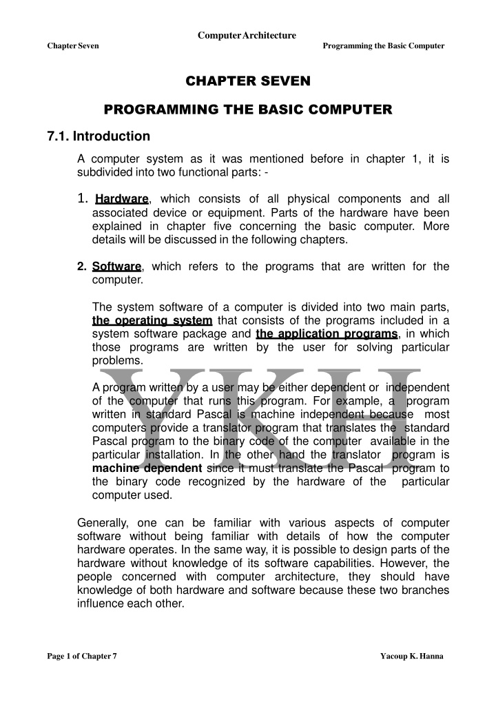
ComputerArchitecture ChapterSeven Programming the Basic Computer CHAPTER SEVEN PROGRAMMING THE BASIC COMPUTER 7.1. Introduction A computer system as it was mentioned before in chapter 1, it is subdivided into two functional parts: - 1. Hardware, which consists of all physical components and all associated device or equipment. Parts of the hardware have been explained in chapter five concerning the basic computer. More details will be discussed in the following chapters. 2. Software, which refers to the programs that are written for the computer. The system software of a computer is divided into two main parts, the operating system that consists of the programs included in a system software package and the application programs, in which those programs are written by the user for solving particular problems. A program written by a user may be either dependent or independent of the computer that runs this program. For example, a written in standard Pascal is machine independent because computers provide a translator program that translates the standard Pascal program to the binary code of the computer available in the particular installation. In the other hand the translator machine dependent since it must translate the Pascal program to the binary code recognized by the hardware of the computer used. program most program is particular Generally, one can be familiar with various aspects of computer software without being familiar with details of how the computer hardware operates. In the same way, it is possible to design parts of the hardware without knowledge of its software capabilities. However, the people concerned with computer architecture, they should have knowledge of both hardware and software because these two branches influence each other. Page 1 of Chapter7 Yacoup K.Hanna
ComputerArchitecture ChapterSeven Programming the Basic Computer In spite of that, the computer executes only the programs that are written in binary form, there are variety types of programming languages that a programmer can write his program. In these cases there must be a translator to translate these programs to the binary form before the computer can execute them. Programs written for computer may be in one of the following forms: - 1. Binary Code form. This is the machine language form, which is defined as a collection of all the fundamental instructions that the machine can execute, expressed together with the operands as a pattern of 1's and 0's. 2. Octal or Hexadecimal Code form. This achieved by translating of the binary code to the equivalent octal or hexadecimal representation. 3. Symbolic Code form (Assembly Language) In this form, the alphanumeric equivalent of the machine language is used. Alphanumeric mnemonics are used as an aid to the programmer, instead of the1's and 0's that the machine interpret. Each symbolic instruction can be translated into one binary coded instruction. The translator that translates the program from assembly language to machine language called Assembler. 4. High-Level Programming Languages These programming languages are closer to the programmer language and far from the machine language. These languages reflects the procedures used in solution of problems rather than be concerned with the computer hardware behavior. Examples of these languages are C, Pascal, Fortran etc. Programs in these programming languages are written in a sequence of statements, each statement must be translated into a sequence of binary instructions before the program can be executed in a computer. The program that translates a high-level language program to binary called a Compiler. Page 2 of Chapter7 Yacoup K.Hanna
ComputerArchitecture Chapter Seven Programming the Basic Computer 2. Machine Language A program in machine language is a sequence of instructions and operands in binary that list the exact representation of instructions as they appear in computer memory. A program of adding two numbers ((13+(-2)) is used to explain the four forms listed in section 7.1 using the basic computer. 1. Table 7.1 shows a binary program for adding the two numbers. Here the program is stored in the memory from location 0 to 6. Looking in this type of program, there is a difficulty to understand what is to be achieved when executed. However, the computer hardware recognizes this type of instruction code. Table 7.1 Binary program location 0000 00000000 0000 00000001 0000 00000010 0000 00000011 0000 00000100 0000 00000101 0000 0000 0110 Instruction Code 0010 0000 00000100 0001 0000 00000101 0011 0000 00000110 0111 0000 00000001 0000 0000 00010011 1111 1111 11111110 0000 0000 0000 0000 2. Table 7.2 shows a hexadecimal program for adding the two numbers. The hexadecimal representation of the program is more convenient to use than the binary form for the programmer; however, one must convert each hexadecimal digit to its equivalent 4-bit number when the program is entered into the computer. Table 7.2 Hexadecimal Program location 000 001 002 003 004 005 Instruction 2004 1005 3006 7001 0013 FFFE 006 0000 Page 3 of Chapter7 Yacoup K.Hanna
ComputerArchitecture ChapterSeven Programming the Basic Computer 3. Table 7.3 shows a program with symbolic operation codes for adding the two numbers instead of their binary or hexadecimal equivalent. Here the address parts of memory-reference instructions, as well as operands, remain in their hexadecimal value. A column of comments is included for explaining the function of each instruction. Symbolic programs are easier and preferable to handle. These symbols can be converted to their binary code equivalent to produce the binary program. Table 7.3 Program with Symbolic Operation Codes location Instruction 000 LDA 004 Loud first operand Into AC 001 LDD 005 Add second operand to AC 002 STA 006 Store sum in location 006 003 HLT Halt computer 004 0013 The first operand 005 FFFE The second operand 006 0000 Store the sum here Comments Note. Negative numbers must be converted to binary in the signed 2's complement representation in the above three programming forms. 4. Table 7.4 shows an assembly language program for adding the above two numbers. The symbols ORG, DEC, and END are called Pseudo Instructions and not a machine instructions. The purpose of ORG Pseudo instruction is to specify an origin, i.e. indicates the memory location of the first instruction of the program is below it. The purpose of DEC Pseudo instruction is to specify a decimal operand. The purpose of END Pseudo instruction is to indicate the end of the program. The three lines having symbolic addresses A, B, and C, their value is specified by they being present as a label in the first column. Page 4 of Chapter7 Yacoup K.Hanna
ComputerArchitecture ChapterSeven Programming the Basic Computer Table 7.4 Assembly Language Program location Instruction ORG 0 LDA A ADD B STA C HLT A, DEC 13 B, DEC -2 C, DEC 0 Comments /Origin of program is location 0 /Load operand from location A /Add operand from location B /Store sum in location C /Halt computer /First decimal operand /Second decimal operand /Sum stored in location C END /End of symbolic program 5. Table 7.5 shows an equivalent FORTRAN program for adding the two numbers. The FORTRAN program is translated into the binary values listed in the program of table 7.1, by what is called a Compiler Program. Table 7.5 Fortran Program INTEGER A, B, C DATA A, 13 B, -2 C = A + B END 7.3. Assembly Language Every computer has its own particular assembly language. The rules for writing assembly language programs are documented and published in manuals which are usually available from the computer manufacturer. The rules of an assembly language for the basic computer are the following: - The line of an assembly language program is divided to three columns called fields as follows: - Page 5 of Chapter7 Yacoup K.Hanna
ComputerArchitecture ChapterSeven Programming the Basic Computer 1, The Label Field. This field may be empty or it may specify a symbolic address. A symbolic address has the following characteristics: - a. It consists up to three alphanumeric characters, the first character must be a letter, and the other two if they exist may be letters or numerals. b. The programmer chooses the symbol arbitrarily. c. A symbolic address is terminated by a comma. 2. The Instruction Field. This field specifies a machine instruction or a pseudo instruction. The instruction field may specify one of the following: - a. A memory reference instruction (MRI). b. A register reference Instruction (RRI). c. Input-output instruction (IOI). d. A pseudo instruction with or without operand. A memory reference instruction (MRI) occupies two or three symbols separated by spaces: - a. The first part must be a three letter symbol defining an MRI. b. The second part is the symbolic address, which specifies the memory location of an operand. c. The third part is the letter I, this may or may not present. If it's present, it denotes indirect address, while if I is missing, it denotes direct addressing. Example AND A1 AND ABCI ADDA Direct address MRI Indirect addressMRI Direct address MRI A non-MRI or RRI & IOI are defined as those instructions that do not have an address part, and presented by a three letter symbol only in the instruction field. Example CMA non-MRI(RRI) OUT non-MRI (IOI) Page 6 of Chapter7 Yacoup K.Hanna
ComputerArchitecture ChapterSeven Programming the Basic Computer pseudo instruction as mentioned before is not a machine instruction but an instruction which gives information to the assembler about some phase of the translation. There are four pseudo instructions as shown in table 7.6. Table 7.6 Symbol Information for the Assembler N indicates the memory location for the instruction or operand listed in the following line. Indicates the end of the program. N indicates the decimal signed number to be converted to binary. N indicates the hexadecimal signed number to be converted to binary. ORG N END DECN HEXN 3. The Comment Field. This field may be empty or it may include a comment. Comments must be preceded by a slash for the assembler to recognize the beginning of a comment field. Comments are inserted for explanation process only and are neglected during the binary translation process. Homework Translate the following assembly language program to subtract two numbers to its equivalent binary from. /Origin of program is location300 /Load subtrahend toAC /Complement AC /IncrementAC /Add minuend to AC /Store difference /Halt computer /Minuend /Subtrahend /Difference stored here /End of symbolic program ORG 300 LDASUB CMA INC ADDMIN STA DIF HLT DEC 23 DEC -2 HEX0 END MIN, SUB, DIF, Page 7 of Chapter7 Yacoup K.Hanna
ComputerArchitecture Chapter Seven Programming the Basic Computer 3. The Assembler and the Compiler Programs The Assembler Program is a program that translates a symbolic language program called the source program into binary program called the object program. An assembler is a program that operates on character strings and produces an equivalent binary interpretation. A Compiler Program is a system program that translates a program written in a high level programming language such as Pascal to a machine language program. A compiler may use an assembly language as an intermediate step in the translation or may translate the program directly to binary. 4. Programming Arithmetic and Logic Operations Depending on the computer, some of them perform a given operation with one machine instruction; others may require a large number of machine instructions to perform the same operation. For example the four basic arithmetic operations (addition, subtraction, multiplication, and division), there are some computers which have machine instruction to add, subtract, multiply, and divide while other computers such as the basic computer have only one arithmetic instruction, such as ADD and the remaining three operations must be implemented by a programs. Operations that are executed with one machine instruction are said to be implemented by hardware, while those operations that are executed by a program are said to be implemented by software. Hardware implementation is more costly than software implementation because of the additional circuits needed to implement the operation, while software implementation has a drawback of long execution time results from more instructions needed to implement the operation. In this section, we will demonstrate the software implementation for some of arithmetic and logic operation using the basic computer. Page 8 of Chapter7 Yacoup K.Hanna
ComputerArchitecture Chapter Seven Programming the Basic Computer 1. Multiplication Operation To simplify the process, assume unsigned positive binary numbers and each number have no more than 8-bits so the result of multiplication does not exceeds the word capacity of 16-bits. The program for multiplying two numbers based on the procedure used to multiply numbers with paper and pencil. The following example with four significant process. explains this multiplication Multiplicand X = 00000111 Multiplier Y = 00001010 00000000 00001110 00000000 00111000 01000110 As shown in the above example, the multiplication process consists of checking the bits of the multiplier Y and adding the multiplicand X shifted left from one line to the next. A memory location denoted by P is reserved to store intermediate sums, since the computer can add only two numbers at a time. The intermediate sums are called partial products since they hold a partial product until all numbers are added. The following example shows how the result of multiplication is achieved in the memory location P for four significant digit of multiplier and multiplicand. Initial value of P P after of 1stpass P after of 2ndpass P after of 3rdpass P after of 4thpass 00000000 00000000 00001110 00001110 0100 0110 Final Result Note. The computer can use numbers with eight significant bits to produce a product of up to 16 bits. Page 9 of Chapter7 Yacoup K.Hanna
ComputerArchitecture ChapterSeven Programming the Basic Computer The flowchart shown in figure 7.1 explains the step-by-step the multiplication operation. CTR -8 P 0 E 0 AC Y cir EAC Y AC =1 0= E P P +X E 0 AC X cil EAC X AC CTR CTR + 1 Stop 0 =0 CTR Figure 7.1 Page 10 of Chapter7 Yacoup K.Hanna
ComputerArchitecture ChapterSeven Programming the Basic Computer Initially, location X holds the multiplicand and location Y holds the multiplier. A counter CTR is set to -8 and location P is cleared to zero. The following program lists the instructions for multiplying two unsigned numbers X = 07 & Y = 0A. ORG200 CLE LDA Y CIR STAY SZE BUN ONE BUNZRO LDA X ADD P STA P CLE LDAX CIL STAX ISZ CTR BUNLOP HLT /Clear E /Load multiplier /Shift multiplier bit toE /Store shifted multiplier /Check if the shifted bit in E iszero /If the bit is one; go to ONE /If the bit is zero; go to ZRO /Load multiplicand /Add to partial product /Store partial product /Clear E /Load multiplicand /Shift left /Store shifted multiplicand /Increment counter /For counter not zero; repeat loop /If counter is zero; Halt /This location serves as a counter /Location of multiplicand /Location of multiplier /Location of the product LOP, ONE, ZRO, CTR, DEC -8 X, Y, P, HEX 0007 HEX000A HEX0 END Note The above program to be a general program for multiplying any two unsigned numbers; the initialization of the multiplicand and multiplier into locations X & Y respectively must be included. The initialization process also must include the initialization of the counter CTR to -8 and P to zero. After generalizing the program according to the note above, the resultant program will demonstrate the software implementation of the multiplication operation. Page 11 of Chapter7 Yacoup K.Hanna
ComputerArchitecture Chapter Seven Programming the Basic Computer 2. Double-Precision Addition A double precision number is a number that stored in two memory words of the memory. To add two double precision numbers; first, every number is placed in two consecutive memory locations, AL & AH for the first number and BL & BH for the other; in which AL & BL holds the 16 least significant bits ( b15 b0) and BL & BH holds the 16 most significant bits ( b31 b16) of the twonumbers. The program for adding two numbers is listed below. First the two low-order portions are added and the carry transferred into E, the content of AC stored into the memory location CL (the 16 least significant bits of the sum). AC is cleared and the bit in E is circulated into the least significant bit of the accumulator AC (0). The two high-order portions are then added to the carry and the content of AC stored into the memory location CH (the 16 most significant bits of the sum). LDA AL ADD BL STA CL CLA CIL ADD AH /Add A high and carry ADD BH /Add B high STA CH /Store in C high HLT xxxx /Location of the low significant part of the 1stnumber AH, xxxx /Location of the high significant part of the 1stnumber BL, yyyy /Location of the low significant part of the 2ndnumber BH, yyyy /Location of the high significant part of the 2ndnumber CL, - /Location of the low significant part of the result CH, - /Location of the high significant part of the result /load A low /Load B low, carry in E /Store in C low /Clear AC /Circulate to bring carry into AC (0) /Halt the computer AL, Page 12 of Chapter7 Yacoup K.Hanna
ComputerArchitecture Chapter Seven Programming the Basic Computer 3. Logic Operations In chapter six it is shown that the basic computer has three machine instructions that perform logic operations: AND, CMA, and CLA. Also LDA instruction can be considered as logic operation that transfers a logic operand into the AC. Any logic function can be implemented using the AND and complement operation CMA. Example Write a program to forms the OR logic operation of two logic 16-bit operands A & B given that A B = (A B). The Program /load the first operand A intoAC /Complement to get A complement ( A) /Store in temporary location TEM /load the second operand B intoAC /Complement to get B complement (B ) /AND with the content of TEM ( A B) /Complement the result to obtainA (AB) = A B /Location of the first operand /Location of the second operand LDA A CMA STATEM LDA B CMA ANDTEM CMA xxxx xxxx A, B, In a similar manner, the other logic operations can be implemented. 4. Shift Operations The basic computer as it was shown before contains only the circular-shift instructions (CIR & CIL) which executes the circular- shift operations. The logical and arithmetic shift operations can be programmed with a number of the computer instructions as follows: Page 13 of Chapter7 Yacoup K.Hanna
ComputerArchitecture Chapter Seven Programming the Basic Computer a. Logical Shift operations These shift operations requires zeroes to be loaded to the extreme positions. This is accomplished by clearing E and circulating the AC & E. Examples (1) The logical shift-right operation can be implemented by the following two instructions: CLE CIR (2) The logical shift-left operation can be implemented by the following two instructions: CLE CIL b. Arithmetic Shift operations These shift operations depends on how the negative numbers are represented. As mentioned before the basic computer uses the 2's complement representation for the negative numbers. (1) Arithmetic right-shift The rules for arithmetic right-shift states that the sign bit in the leftmost position remain unchanged and the sign bit itself is shifted into the high-order bit position of the number. The program for the arithmetic right-shift requires setting E to the same value as the sign bit and circulate right as follows: CLE SPA CME CIR /Clear E to 0 /Skip if AC is positive; E remains 0 /AC is negative; set E to 1 /Circulate E &AC Page 14 of Chapter7 Yacoup K.Hanna
ComputerArchitecture ChapterSeven Programming the Basic Computer (2) Arithmetic left-shift The rules for arithmetic left-shift are that the added bit in the least significant position must be 0. This is accomplished by clearing E before circulate-left operation. Also the sign bit must not change during this shift. After the circulate instruction is executed, the sign bit moves into E, then it is necessary to compare the sign bit with the value of E after the operation. If the two bits are equal, the arithmetic shift has been correctly implemented. If they are not equal, an overflow occurs (i.e. the original number was too large). The simplified program for the arithmetic left-shift is as follows: CLE CIL /Clear E to 0 /Circulate E &AC 5. Subroutines A Subroutine can be defined as a set of instructions that can be used in a program many times. A Subroutine has general characteristics such as: 1. It consists of a self contained sequence of instructions that carries out a given task. 2. A branch can be made to the subroutine from any part of the main program. 3. All computers subroutine call to facilitate subroutine entry and return to the main program. provide special instructions commonly called 4. The procedure for branching to a subroutine and returning to the main program is referred to as a subroutine linkage. 5. The last instruction of the subroutine performs an operation commonly called subroutine return. For basic computer the instruction BSA (Branch and Save return Address) is the link instruction between the main program and the subroutine. Page 15 of Chapter7 Yacoup K.Hanna
ComputerArchitecture ChapterSeven Programming the Basic Computer Table 7.7 shows subroutines. This program contains a subroutine that shifts the content of the accumulator four times to the left which is useful operation for processing binary-coded decimal characters. Table 7.7 a program that demonstrates the use of numbers or alphanumerical Location Label Instruction ORG 200 LDA X BSA SH4 STA X LDA Y BSA SH4 STA Y HLT HEX1234 HEX4321 Comments /Main program /Load X /Branch To subroutine /Store shifted number /LoadY /Branch to subroutine a second time /Store shifted number /Halt the computer 200 201 202 203 204 205 206 207 208 X, Y, /Subroutine to shift left 4 times /Store return address here /Circulate leftonce /Circulate leftonce /Circulate leftonce /Circulate leftonce /Set AC(3-0) to zero /Return to main program /Mask operand 209SH4, 20A 20B 20C 20D 20E 20F 210 HEX0 CIL CIL CIL CIL ANDMSK BUN SH4I HEXFFF0 END MSK, How the program is executed 1. The first number (HEX 1234) contained at location X (HEX 207) is loaded to the accumulator AC by the instruction LDAX. 2. When the next instruction BSASH4 is executed, the control unit stores the return address (HEX 202) into the location defined by the symbolic address SH4 (location HEX 209), also transfers the value of SH4+1 (i.e. HEX 20A) into the program counter PC. 3. After execution of the instruction BSA SH4, the subroutine is executed starting from location 20A (since this is the content of PC in the next fetch cycle). a. The four shift instructions (CIL) circulate the content of AC four times to the left. Page 16 of Chapter7 Yacoup K.Hanna
ComputerArchitecture ChapterSeven Programming the Basic Computer b. In order to accomplish a logical shift instruction, the four least significant bits must be zero. This is achieved by masking FFF0 with the content of AC using the AND operation (the instruction at location HEX 20E). c. The last instruction BUN SH4 I (indirect branch unconditional instruction) returns the computer to the main program (i.e. to location HEX 202). 4. The main program continues by storing the shifted number into location X. 5. A new number (HEX 4321) from location Y (HEX 208) is then loaded into the AC and another branch is made to the subroutine. The same procedure will be repeated, but in this case the location SH4 will contain the return address HEX 205 since this is now the location of the next instruction after BSA. After the subroutine is executed the subroutine returns to the main program at location 205. 6. When the execution of the program is completed the contents of locations 207 & 208 are HEX 2340 & HEX 3210 respectively. 7.6. Input-Output Programming The character is stored in the computer as an 8-bit code. The character enters the computer by an INP instruction and transferred to the output device using an OUT instruction. The following set of instructions, input a character and stores it in memory. SKI BUNCIF INP OUT STACHR HLT ---- /check input flag /flag = 0, branch to checkagain /flag = 1, input character /printcharacter /storecharacter CIF, CHR, /store character here The program starts with the instruction SKI which checks the input flag to see if a character is available to transfer. If the input flag is 1, the next instruction BUN is skipped. The INP instruction transfers the binary-coded character into AC (0-7). By the OUT instruction, the character is printed by the output device. If the input flag is 0, the next instruction BUN is executed and a branch to return and check the input flag again. Page 17 of Chapter7 Yacoup K.Hanna
ComputerArchitecture ChapterSeven Programming the Basic Computer The two instructions SKI & BUN will be executed many times before a character is transferred into the accumulator, because the input device is much slower than the computer. The following set of instructions, print a character initially stored in memory. /load character intoAC /check output flag /flag = 0, branch to checkagain /flag = 1, output character LDACHR SKO BUNCOF OUT HLT HEX0057 COF, CHR, /character isW The program starts with the instruction LDA to load the binary-coded character into the AC from the memory location CHR. The instruction SKO checks the output flag, if its 1, the character is transferred from AC to the printer. If the output flag is 0, the computer remains in a two instruction loop (SKO & BUN) checking the flag bit. Character Manipulation To pack two characters in one memory word for the purpose of character manipulation, the subroutine named IN2 that inputs two characters and packs them into the AC is shown below. /Subroutine entry /check input flag /flag = 0, branch to checkagain /flag = 1, input character /output character /Shift left four times /Shift left four times /check input flag /flag = 0, branch to checkagain /flag = 1, input character /output character /Return IN2, FST, - SKI BUNFST INP OUT BSA SH4 BSA SH4 SKI BUNSCD INP OUT BUN IN2I SCD, It is clear that this subroutine calls twice the subroutine SH4 to shift the accumulator left eight times. Page 18 of Chapter7 Yacoup K.Hanna
ComputerArchitecture Chapter Seven Programming the Basic Computer Program Interrupt The interrupt facility is useful when two or more programs reside in the memory at the same time. Even though two or more programs may reside in the computer memory, only one program can be executed at a given time and this program is referred to as the running program. The other programs are usually waiting for input or output data. The function of the interrupt facility is to take care of the data transfer of one (or more) program while another program is currently being executed. The running program must include an ION instruction to turn the interrupt on. If the interrupt facility is not used, the program must include an IOF instruction to turn it off. The interrupt facility allows the running program to proceed until the input or output device sets its ready flag. Whenever a flag is set to 1, the computer completes the execution of the instruction in progress and then acknowledges the interrupt. The result of this action is that the return address is stored in location 0. The instruction in location 1 is then performed; this initiates a service routine for the input or output transfer. The service routine can be stored anywhere in memory provided a branch to the start of the routine is stored in location 1. The service routine must have instructions to perform the following tasks: - 1. Save the contents of processor registers. 2. Check which flag is set. 3. Service the device whose flag is set. 4. Restore contents of processor registers. 5. Turn the interrupt facility on. 6. Return to the running program. The following program listed in table 7.8 explains an interrupt services. 1. Location 0 is reserved for the return address. 2. Location 1 has a branch instruction to the beginning of the service routine SRV. 3. The ION instruction found in the main program turns the interrupt on. 4. It is supposed an interrupt occurs while the computer is executing the instruction in location 103. Page 19 of Chapter7 Yacoup K.Hanna
ComputerArchitecture ChapterSeven Programming the Basic Computer 5. The interrupt cycle stores the address of the following instruction (HEX 104) in location 0 and branches to location 1. 6. The branch instruction in location 1 branches to the service routine SRV. 7. The service routine performs the six tasks listed above. Table 7.8 Location Label Instruction 0 1 100 101 102 103 104 . . . 200 SRV, Comment /return address stored here /branch to service routine /portion of runningprogram /turn on interrupt facility ZRO, - BUNSRV CLA ION LDAX ADDY STAZ . . /interrupt occur here /program returns here after interrupt /interrupt service here /store content ofAC /move E into AC (15) /store content of E /check input flag /flag is off, check next flag /flag is on, input character /print character /store it in input buffer /increment input pointer /check output flag /flag is off, exit /load character from output buffer /output character /increment output pointer /restore value of AC(15) /shift it to E /restore content ofAC /turn interrupt on /return to running program /AC is stored here /E is stored here /pointer of input buffer /pointer of output buffer STASAC CIR STASE SKI BUNNXT INP OUT STA PT1I ISZ PT1 SKO BUN EXT LDA PT2I OUT ISZ PT2 LDA SE CIL LDASAC ION BUN ZROI - - - - NXT, EXT, SAC, SE, PT1, PT2, A typical computer may have many more input and output devices connected to the interrupt facility. Page 20 of Chapter7 Yacoup K.Hanna
ComputerArchitecture Chapter Seven Programming the Basic Computer Problems 7.1. The following program is stored in the memory unit of the basic computer. Show the contents of the registers AC, PC, and IR in hexadecimal, after each instruction is executed. All numbers listed in the program are in hexadecimal. Location Instruction 010 011 012 013 014 015 016 017 CLA ADD 016 BUN 014 HLT AND 017 BUN 013 C1A5 93C6 2. For the following program: a. Explain in words what the following program accomplished when it is executed. b. What is the value of location CTR when the computer halts? c. List the hexadecimal code of the translated program. ORG100 CLE CLA STA CTR LDA WRD SZA BUN ROT BUN STP CIL SZE BUN AGN BUN ROT CLE ISZ CTR SZA ROT, AGN, STP, CTR, WRD, Page 21 of Chapter7 Yacoup K.Hanna
ComputerArchitecture ChapterSeven Programming the Basic Computer BUN ROT HLT HEX 0 HEX 62C1 END 7.3. The following program is in hexadecimal code. The computer executes the instructions starting from address 100. What are the content of AC and the memory word at address 103 when the computer halts? Location Instruction 100 101 102 103 104 105 106 5103 7200 7001 0000 7800 7020 C103 4. Write an assembly program to multiply two positive numbers by a repeated addition method. For example, to multiply 5 4, the program evaluates the product by adding 5 four times, 5+5+5+5. 5. Write an assembly program to multiply two unsigned positive numbers, each with 16 significant bits, to produce an unsigned double-precision product. 6. Write an assembly program to subtract two double-precision numbers. 7. Write an assembly program that evaluates the logic exclusive-OR of two logic operands. 8. Write a subroutine to circulate E and AC four times to the right. If AC contains hexadecimal 079C and E = 1, what are the contents of AC and E after the subroutine is executed. 9. Write an assembly program to accept input characters. Pack two characters in one word and store them in consecutive locations in a memory buffer. The first address of the buffer is (400)16. The size of the buffer is (512)10 words. If the buffer overflows, the computer should halt. Page 22 of Chapter7 Yacoup K.Hanna
ComputerArchitecture ChapterSeven Programming the Basic Computer 7.10. Translate the service routine SRV from table 7.8 to its equivalent hexadecimal code. Assume that the routine is stored staring from location 200. 7.1. The following program is stored in the memory unit of the basic computer. Show the contents of the registers AC, PC, and IR in hexadecimal, after each instruction is executed. All numbers listed in the program are in hexadecimal. Location Instruction 010 011 012 013 014 015 016 017 CLA ADD 016 BUN 014 HLT AND 017 BUN 013 C1A5 93C6 Solution Contents of Registers AC, PC, and IR after the Execution of the Instruction Location Instruction AC 0000 C1A5 C1A5 8184 8184 8184 PC 011 012 014 013 015 013 IR 7800 1016 4014 7001 0017 4013 010 011 012 013 014 015 016 017 CLA ADD 016 BUN 014 HLT AND 017 BUN 013 C1A5 93C6 Note 1. The IR column is taken from the hexadecimal presentation of the given instruction (see table 6.2 in chapter 6). Page 23 of Chapter7 Yacoup K.Hanna
ComputerArchitecture ChapterSeven Programming the Basic Computer 2. The PC column calculated due to the fetch phase PC PC + 1 as in case of CLA, ADD, and AND instructions or due to the fetch phase with the execution result of the instruction as in the case of BUN instruction as follows (taking the example of BUN 014): a. In fetch phaseAR IR (0-11), i.e.AR = 014. b. After instruction execution PC AR, i.e. PC = 014. 3. For the AC, its contents are changed according to the instruction function. For the following program: a. Explain in words what the following program accomplished when it is executed. b. What is the value of location CTR when the computer halts? c. List the hexadecimal code of the translated program. 2. ORG100 CLE CLA STA CTR LDA WRD SZA BUN ROT BUN STP CIL SZE BUN AGN BUN ROT CLE ISZCTR SZA BUN ROT HLT HEX0 HEX 62C1 END ROT, AGN, STP, CTR, WRD, Solution a.The program counts the number of 1's in the number stored in location WORD. b.The counter CTR = 6, since the number (62C1) contains 6 one's. c. Assembly Language Program Location Instruction ORG100 Corresponding Hexadecimal Program Location Content Page 24 of Chapter7 Yacoup K.Hanna
ComputerArchitecture ChapterSeven Programming the Basic Computer CLE CLA STA CTR LDA WRD SZA BUN ROT BUN STP CIL SZE BUN AGN BUN ROT CLE ISZ CTR SZA BUN ROT HLT HEX 0 HEX 62C1 END 100 101 102 103 104 105 106 107 108 109 10A 10B 10C 10D 10E 10F 110 111 7400 7800 3110 2111 7004 4107 410F 7040 7002 410B 4107 7400 6110 7004 4107 7001 0000 62C1 ROT, AGN, STP, CTR, WRD, 7.3. The following program is in hexadecimal code. The computer executes the instructions starting from address 100. What are the content of AC and the memory word at address 103 when the computer halts? Location 100 101 102 103 104 105 106 Instruction 5103 7200 7001 0000 7800 7020 C103 Solution To understand the function of the program, we have to translate the binary program to an assembly program. Hexadecimal Program Location Assembly Language Program Location ORG 100 100 BSA 103 101 CMA 102 HLT 103 HEX 0000 104 CLA 105 INC 106 BUN 103I Instruction Instruction 100 101 102 103 104 105 106 5103 7200 7001 0000 7800 7020 C103 The contents of: 1. The memory location H 103 = 0101 2. The content of the accumulator AC = HEX FFFE Explanation of how the program is executed Page 25 of Chapter7 Yacoup K.Hanna
ComputerArchitecture ChapterSeven Programming the Basic Computer 1. The execution of instruction BSA103 do the following: a. Stores the address of the next instruction in sequence (HEX 101) which is available in PC into a memory location specified by the effective address (Location HEX 103 in memory) i.e. memory location 103 contains HEX 0101. b.The effective address plus 1 is then transferred to PC to serve as the address of the first instruction in the subroutine i.e. PC = HEX 104. 2. Executing CLAinstruction (ClearAccumulator) i.e. AC = 0000. 3. Executing INC instruction (IncrementAccumulator) i.e. AC = 0001. 4. Executing BUN instruction (Indirect Branch Unconditional) when this instruction is executed, control goes to the indirect phase to read the effective address at location 103, where it finds the previously saved address 101. 5. The instruction at location 101 is executed (i.e. CMA), thenAC =FFFE. 6. Then the HLT is executed and the program halts. 7. Then location 103 in the memory will contain 0101, and AC=FFFE 7.4. Write an assembly program to multiply two positive numbers by a repeated addition method. For example, to multiply 5 4, the program evaluates the product by adding 5 four times, 5+5+5+5. Solution AssemblyProg. Loc. Instruction Comment ORG 100 LDA MUL /Load multiplier in location MUL inAC CMA /Complement AC INC /Increment AC STA MUL /Store AC in location MUL CLA /Clear AC LOP, ADD MUC /Add multiplicand MUC to AC ISZ MUL /Increment the counter MUL BUN LOP /Counter not zero; repeat loop STA PRO /Store the result in location PRO HLT /Halt MUL, DEC 4 /Multiplier stored here ( as counter) MUC, DEC 5 /Multiplicand stored here PRO, - /Product stored here HexadecimalProg. Loc. Instruction 100 101 102 103 104 105 106 107 108 109 10A 10B 10C 210A 7200 7020 310A 7800 110B 610A 4105 310C 7001 0004 0005 - 7.5. Write an assembly program to multiply two unsigned positive numbers, each with 16 significant bits, to produce an unsigned double-precision product. Solution:Assume the Multiplier = Y & the Multiplicand = X, the Product stored in two words of memory PH & PL ORG 200 LOP, CLE /Clear E LDA Y /Load multiplier CIR /Shift multiplier bit to E STA Y /Store shifted multiplier SZE /Check if the shifted bit in E is zero BUN ONE /If the bit is one; go to ONE BUN ZRO /If the bit is zero; go to ZRO Page 26 of Chapter7 Yacoup K.Hanna
ComputerArchitecture ChapterSeven Programming the Basic Computer ONE, /Load multiplicand /Add low part of partial product PL to the shifted multiplicand /Store in the PL /Clear AC /Shift the carry to AC(0) /Add the carry to high part of partial product PH /Store in the PH /Clear E /Load multiplicand /Shift left d /Store shifted multiplicand /Increment counter /For counter not zero; repeat loop /If counter is zero; Halt /This location serves as a counter /Location of multiplicand /Location of multiplier /Location of the low part of product /Location of the high part of product LDA X ADD PL STA PL CLA CIL ADDPH STA PH CLE LDA X CIL STA X ISZ CTR BUNLOP HLT DEC -16 HEX 0007 HEX 000A HEX 0 HEX 0 END ZRO, CTR, X, Y, PL, PH, 7.6. Write an assembly program to subtract two double-precisionnumbers. Solution Assume two positive numbers, the first number A stored in two consecutive memory locations AH & AL, the second number B stored in two consecutive memory locations BH & BL, and the result of subtraction stored in two consecutive memory locations CH & CL. Loc. Instruction Comment ORG100 LDA BL CMA INC STABL LDABH CMA SZE INC STABH /load B low /Complement B low (1's complement) / obtain 2's complement of B low /Store in BL / load B high /Complement B high (1's complement) 2nd numberB. This part of the program is to 2's obtain complement of the the /Skip if E is zero /Increment AC if E = 1 /Store in BH /load A low /Load B low, carry in E /Store in C low /ClearAC /Circulate to bring carry into AC (0) /Add A high and carry /Add B high /Store in C high /Halt the computer /Location of the low significant part of the 1stnumber /Location of the high significant part of the 1stnumber LDA AL ADD BL STA CL CLA CIL ADDAH ADDBH STA CH HLT xxxx xxxx AL, AH, Page 27 of Chapter7 Yacoup K.Hanna
ComputerArchitecture ChapterSeven Programming the Basic Computer BL, BH, CL, CH, yyyy yyyy - - /Location of the low significant part of the 2ndnumber /Location of the high significant part of the 2ndnumber /Location of the low significant part of the result /Location of the high significant part of the result 7.7. Write an assembly program that evaluates the logic exclusive-OR of two logic operands. Solution X Y = X Y X Y = X Y X Y = X Y X Y Location Instruction ORG 200 LDA X CMA STR XCO LDA Y CMA STR YCO AND X CMA STR TMP LDA Y AND XCO CMA AND TMP CMA STR EOR Comment /Load the first operand X /complement to get X /Store in the temporary locationXCO /Load the second operand Y /complement to get Y /Store in the temporary location YCO /And with X to get X Y /Complement to get X Y /Store in the temporary location TMP /Load the second operand Y /And with X to get X Y /Complement to get X Y /And with TMP to get X Y X Y /Complement to get X Y X Y /Store in the location EOR = X Y Page 28 of Chapter7 Yacoup K.Hanna
ComputerArchitecture ChapterSeven Programming the Basic Computer HLT xxxx yyyy - - - /Halt the program /Location of the first operand /Location of the second operand /Temporary location of X /Temporary location of Y /Temporary location of X Y X, Y, XCO, YCO, TMP, 7.8. Write a subroutine to circulate E and AC four times to the right. If AC contains hexadecimal 079C and E = 1, what are the contents of AC and E after the subroutine is executed. Solution Content ofAC Content of E Comment Loc. Instruction ORG 300 LDA CAR /Load AC by carry 1 0001 x CIR /Set the carry to 1 0000 or 8000 1 LDA NUM / Load AC by the number HEX 079C 079C 1 CIR /Circulate E & AC to the right 83CE 0 CIR /Circulate E & AC to the right 41E7 0 CIR /Circulate E & AC to the right 20F3 1 9079 1 CIR /Circulate E & AC to the right STA NUM /Store the content of AC in NUM CLA /Clear AC CIL /Circulate to the left i.e. AC(0) E STA CAR /Store the content of E in CAR HLT /Halt the program NUM, HEX 079C /Location of the number Page 29 of Chapter7 Yacoup K.Hanna
ComputerArchitecture ChapterSeven Programming the Basic Computer CAR, HEX 0001 /Location of the carry Therefore the content of: - 1. The accumulator AC = 9079 2. The accumulator extension E = 1 7.9. Write an assembly program to accept input characters. Pack two characters in one word and store them in consecutive locations in a memory buffer. The first address of the buffer is (400)16. The size of the buffer is (512)10 words. If the buffer overflows, the computer should halt. Location Instruction Comment /Load first address of buffer /Initialize the pointer /Go to subroutine IN2 /Store double character word in buffer /Increment pointer LDA ADS STA PTR BSA IN2 STA PTRI ISZ PTR ISZ CTR BUN LOP HLT HEX0 SKI BUNFST INP OUT BSASH4 BSASH4 SKI BUNSCD INP OUT BUN IN2I HEX 0 CIL CIL CIL CIL LOP, /Branch to input more characters /Halt the program /Store return address here /Skip if input flag is on /Branch unconditional if input flag is0 /Input first character /Out first character /Shift left four times /Shift left four more times /Skip if input flag is on /Branch unconditional if input flag is0 /Input second character /Out second character /Return to the main program /Store return address here /Circulate left once /Circulate left second time /Circulate left third time /Circulate left fourth time IN2, FST, SCD SH4, Page 30 of Chapter7 Yacoup K.Hanna
ComputerArchitecture ChapterSeven Programming the Basic Computer /Set AC(12-15) to zero /Return to subroutineIN2 /Mask operand AND MSK BUN SH4 I HEXFFF0 MSK, HEX400 HEX 0 DEC -512 /First address of buffer /Location for pointer /Buffersize ADS, PTR, CTR 7.10. Translate the service routine SRV from table 7.8 to its equivalent hexadecimal code. Assume that the routine is stored staring from location 200. Solution Loc. 0 1 . . . 100 101 102 103 104 Label ZRO, Instruction - BUN SRV Comment Loc. 000 001 . . . 100 101 102 103 104 Inst. - 4200 . . . 7800 F080 2217 1218 3219 /return address stored here /branch to service routine . . . . . . CLA ION LDA X ADD Y STA Z . . . /portion of running program /turn on interrupt facility /interrupt occur here /Program returns here after interrupt . . . 200 . . . . /interrupt service here /store content of AC /move E into AC (15) /store content of E /check input flag /flag is off, check next flag /flag is on, input character /print character /store it in input buffer /increment input pointer /check output flag /flag is off, exit /load character from output . . SRV, STA SAC CIR STA SE SKI BUN NXT INP OUT STA PT1 I ISZ PT1 SKO BUN EXT LDA PT2 I 200 201 202 203 204 205 206 207 208 209 20A 20B 3213 7080 3214 F200 420E F800 F400 B215 6215 F100 4209 A216 NXT, buffer Page 31 of Chapter7 Yacoup K.Hanna
ComputerArchitecture ChapterSeven Programming the Basic Computer OUT ISZ PT2 LDA SE CIL LDA SAC ION BUN ZRO I - - - - xxxx yyyy - /output character /increment output pointer /restore value of AC (15) /shift it to E /restore content of AC /turn interrupt on /return to running program /AC is stored here /E is stored here /pointer of input buffer /pointer of output buffer 20C 20D 20E 20F 210 211 212 213 214 215 216 217 218 219 F400 6216 2214 7040 2213 F080 C000 - - - - xxxx yyyy - EXT, SAC, SE, PT1, PT2, X, Y, Z, Page 32 of Chapter7 Yacoup K.Hanna
