Project Kick-Off Team Meeting Agenda
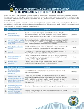
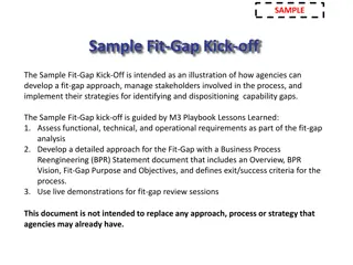
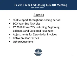
Agenda for the project kick-off team meeting includes introductions, project mission, vision & goals, project description & scope, known stakeholders & risks, project team & org chart, schedule, budget, project management & PMP details."
Download Presentation

Please find below an Image/Link to download the presentation.
The content on the website is provided AS IS for your information and personal use only. It may not be sold, licensed, or shared on other websites without obtaining consent from the author. If you encounter any issues during the download, it is possible that the publisher has removed the file from their server.
You are allowed to download the files provided on this website for personal or commercial use, subject to the condition that they are used lawfully. All files are the property of their respective owners.
The content on the website is provided AS IS for your information and personal use only. It may not be sold, licensed, or shared on other websites without obtaining consent from the author.
E N D
Presentation Transcript
Introduction to SUE/SUDA Engineering\CADD Systems Office
Topics Covered Retired Utility Levels, QC Legacy Laying out utilities using Features and viewing them in Cross Sections Explain SUE and SUDA and the licensing Laying out utilities using SUE and viewing them in the Cross Sections Clash Detection Flex Tables Drainage Preview
Utility Features Utility Features must be turned on using the FDOT Menu Configuration tool for those Features to be available. The menus selected and options to include Survey and Utility Features will trigger selected DGN Libraries (.DGNLIB files) to be loaded when MicroStation is launched.
Utility Levels Changes All utility levels without Quality Levels have been retired. Other utility level names have been updated to for consistency: All power levels have been changed to elec Fiber Optic has been broken out into 3 different types (FOCable, FOElec, and FOTele) Other miscellaneous changes have been made also.
QC Legacy QC Legacy scans the file looking for elements still using old symbology and gives you an opportunity to update them.
Quality Levels Quality Level D: Lowest level of accuracy. Information is obtained from existing utility records. Quality Level C: More accurate than Quality Level D. Information is obtained from topographic surveying of visible utility features. Quality Level B: More accurate than Quality Level C. Information is obtained from the use of scanning technologies. This information can be found in the PPM Ch. 5; Section 5.3: Utility Locates.
Civil Features Approach to Utilities Utilities can be shown in the 3D model and on cross sections if a Feature Definition is defined. 1. Apply Feature Definition to underground utilities in 2D plan view 2. Set an active profile for each underground utility 3. Label Cross Sections with Ancillary Features
Apply Feature to 2D Utility Lines Use the Set Feature Definition tool in the Civil Tools > Horizontal Geometry task menu
Apply Feature Using Complex By Elements If utility lines are made up of many small elements it will be best to chain them together as a single element. You can do this and apply a Feature Definition at the same time using the Complex By Elements
Create Active Profile Use the Profile Offset Transition tool from the Civil Tools > Vertical Geometry task menu to create a profile at a depth of cover. Open Profile view of 2D utility line Click Profile Offset Transition Follow prompts on Cursor Once Created, set new Profile to Active
Cross Section Viewing Once a utility s Feature Definition and Active Profile is set a 3D line of the utility will be created. The Feature Definition also has information on how the line should be displayed in a cross section view. Click Open Cross Section View on the Civil Tools > Corridor Modeling task menu. Follow prompts on cursor to open cross section view Note: The symbology of the utility will not appear correctly until cut to sheets.
What is SUE or SUDA? Subsurface Utility Design and Analysis (SUDA) Subsurface Utility Engineering (SUE) StormCAD Hydraulic Analysis/Design Engineering Conflict Management / Clash Detection SUE Attribution 3D Modeling of underground objects. Integrate with OpenRoads Storm/Sanitary Hydraulic Analysis and Design Hydrology
SUE Model When any of the SUE tools are launched for the first time in a file the user will prompted that a utility model will be created in the design file. Container for Utility data Cannot be undone The utility model will be processed each time the file is opened Save early and often. (MicroStation: File > Save) Utility model could be lost if crash occurs
Results Here you can see the results in the 3D model where water and sanitary sewer were done with SUE and the buried telephone was done using standard Features placed using Horizontal and Vertical Geometry tools.
Extracting Utility Features from Graphics Use SUE s Extract Utilities From Graphics tool to create a 3D model from 2D UTEXRD files. Vertical based on a vertical Offset from existing surface
FDOT SUDA Drainage Tools in Development FDOT is currently developing tools and processes to support the new drainage tools available in SUDA. Features Annotation Reporting Training Until complete continue using current methods
Contact Info Jimmie Prow CADD Support Coordinator Phone no: (850) 414-4863 Toll Free no: (866) 374-3368 extension 4863 email ecso.support@dot.state.fl.us jimmie.prow@dot.state.fl.us web: http://www.dot.state.fl.us/ecso

