Prosthodontics Laboratory Procedures in RPD Construction
This detailed lecture covers the process of duplicating a stone cast in removable partial denture construction. It includes the steps of duplicating materials, flask assembly, impression making, and preparation of the refractory cast. Images illustrate each step for clear understanding of the procedure.

Download Presentation

Please find below an Image/Link to download the presentation.
The content on the website is provided AS IS for your information and personal use only. It may not be sold, licensed, or shared on other websites without obtaining consent from the author.If you encounter any issues during the download, it is possible that the publisher has removed the file from their server.
You are allowed to download the files provided on this website for personal or commercial use, subject to the condition that they are used lawfully. All files are the property of their respective owners.
The content on the website is provided AS IS for your information and personal use only. It may not be sold, licensed, or shared on other websites without obtaining consent from the author.
E N D
Presentation Transcript
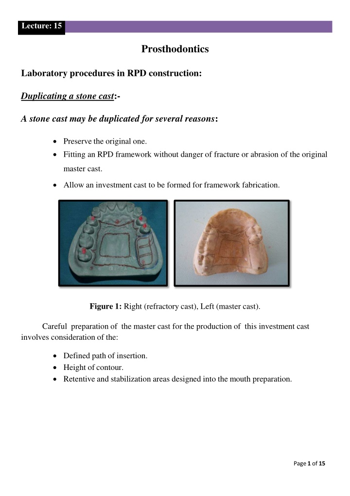
Lecture: 15 Prosthodontics Laboratory procedures in RPD construction: Duplicating a stone cast:- A stone cast may be duplicated for several reasons: Preserve the original one. Fitting an RPD framework without danger of fracture or abrasion of the original master cast. Allow an investment cast to be formed for framework fabrication. Figure 1: Right (refractory cast), Left (master cast). Careful preparation of the master cast for the production of this investment cast involves consideration of the: Defined path of insertion. Height of contour. Retentive and stabilization areas designed into the mouth preparation. Page 1 of 15
Lecture: 15 : Figure 2: master cast after completing relief and block out. Duplicating material and flask: Colloidal material: are made fluid by heating and return to gel when cooling. Silicone material. Figure 3: Right (Silicone material), Left (Colloidal material). The cast to be duplicated must be placed at the bottom of a suitable flask, called a duplicating flask. Care must be taken that the temperature of the duplicating material is not higher than that recommended by the manufacturer to prevent melting and distortion of the blackout material. Page 2 of 15
Lecture: 15 : Impression: To make the impression, a blocked-out master cast is placed on the base of a duplicating flask and the flask is assembled. Figure 4: Left (duplicating flask), Middle (blocked-out master cast placed at the base of a duplicating flask), Right (duplicating flask is assembled). And a steady stream of reversible hydrocolloid is poured into the flask, once filled the flask is placed in a regulated cooling tank up to an hour may be required to fully set the colloid. Figure 5: Left (boiler for melting reversible hydrocolloid), Middle (reversible hydrocolloid is melted), Right (reversible hydrocolloid is poured into the flask). The flask is then disassembled. The master cast is carefully removed with the aid of two knife blades engaging the sides of the cast. Page 3 of 15
Lecture: 15 : Figure 6: Left (flask is removed), Right (the master cast is removed, and mold is ready for pouring the investment material). Duplicating colloids can be reused repeatedly, most laboratories have special equipment to remelt and store the colloid. Colloids also can be prepared with less sophisticated equipment. To employ such techniques, a clean colloid is cut into small pieces and heated in a double boiler until the material reaches a fluid consistency. The resulting sol is then allowed to cool to working temperature, ensuring a suitable flow of the material without melting the Blockout wax. A breakdown temperature of 100 C (212 F) and a working temperature of 63 C (145 F) are suitable for most duplicating materials. Figure 7: Left (clean colloid is cut into small pieces), Middle (heated in a boiler), Right (material reaches a fluid consistency). Page 4 of 15
Lecture: 15 : Refractory cast: This is made from Refractory materials (also termed investments) must be measured and mixed according to the manufacturer s instructions. Figure 8: investment materials measured and mixed according to the manufacturer s instructions. The mold expansion is to match the shrinkage of the associated alloy; the investment material is allowed to harden before removal from the mold. Figure 9: Left (investment material is poured in the mold), Middle (material is allowed to harden), Right (cast removal from the mold). The duplicated model is allowed to dry by placing it in a drying cabinet; Page 5 of 15
Lecture: 15 : Figure 10: Duplicated model is placed in a drying cabinet. Then the refractory cast is dipped in hot beeswax to ensure a smooth, dense surface and to eliminate the need for soaking the cast before the investment process. Figure 11: Left (refractory cast removed from dryness cabinet), Middle (the refractory cast is dipped in hot beeswax), Right (the refractory cast is allowed to dry). Waxing the framework: Before waxing can begin, the design must be transferred from the master cast to the refractory cast. Every effort is made to precisely transfer the outline of the framework to the refractory cast. Page 6 of 15
Lecture: 15 : Figure 12: Design transferred from the master cast to the refractory cast. Care is taken to draw with a minimum of pressure, so the surface of the refractory cast is not damaged. The position of individual clasp tips is the most critical part of the transfer. If appropriate ledges were created during blockout procedures, the placement of retentive clasp tips is much easier and more precise. Spruing: The sprue channel is the opening that leads from the crucible to the cavity in which the framework is to be cast. Figure 13: Sprue is attached to the waxed framework on the refractory cast. Page 7 of 15
Lecture: 15 : General rules for spruing: o Sprues should be large enough that the molten metal in them will not solidify until after the metal in the casting proper has frozen (8-12 gauge round wax) is usually used for multiple spruing of RPD casting. Figure 14: Multiple Sprues is attached to the crucible from above and the waxed framework from below. o Sprues should lead into the mold cavity as directly as possible and still permit a configuration that will induce a minimal amount of turbulence in the stream of molten metal. Figure 15: Sprues lead into the mold cavity directly. Page 8 of 15
Lecture: 15 : o Sprues should leave the crucible form a common point and be attached to the wax pattern at its bulkier section, that is, no thin sections of casting should intervene between two bulky, unsprued portions. Figure 16: Sprues leave the crucible form a common point (red arrow) and attached to the wax pattern at the bulkier section (black arrows). Investing the sprued pattern: The investment must conform accurately to the shape of the pattern and must preserve the configuration of the pattern as a cavity after the pattern itself has been eliminated through vaporization and oxidation. Figure 17: Left (sprued pattern on the refractory cast is poured with investment materials), Right (the refractory cast is completely poured with investment materials). Page 9 of 15
Lecture: 15 : Purpose of investment: o It provides the strength necessary to hold the forces exerted by the entering stream of molten metal until this metal has solidified into the form of the pattern. o It provides a smooth surface for the mold cavity so that the final casting will require as little finishing as possible. o It provides an avenue of escape for most of the gases entrapped in the mold cavity by the entering stream of molten metal. o It, together with other factors, provides necessary compensation for the dimensional changes of the alloy from the molten to the solid, cold state. Burnout: The burnout has three reasons: Drives off the moisture in the mold. It vaporizes and thus eliminates the pattern, leaving a cavity in the mold. It expands the mold to compensate for the contraction of the metal on cooling. The mold should be placed in the oven with the sprue hole down. Figure 18: Mold is placed in the burnout oven with the sprue hole down. Page 10 of 15
Lecture: 15 : The temperature should be maintained for the period recommended by the manufacturer to ensure uniform heat penetration. Figure 19: Mold is placed in the burnout oven for uniform heat penetration. Casting: It is the process of quickly injecting the metal into the mold cavity, the force may be centrifugal or air pressure, in any case too much or too little pressure is undesirable; if too little force is used the mold is not filled before the metal begins to freeze. If too much force, excessive turbulence may result in the entrapment of gases in the casting. Figure 20: Left (metal is heated to melt), Middle (metal is started to melt), Right (the metal is ready to be injected into the mold cavity). Casting recovery: When the casting process is complete, the mold is removed from the casting machine and allowed to cool according to the manufacturer s instructions. Page 11 of 15
Lecture: 15 : At the appropriate time, the outer layer of refractory material is removed by tapping it with a mallet. Figure 21: The refractory material is removed by tapping with a mallet. The remaining investment is then removed by airborne particle abrasion in a self- contained machine manufactured for this purpose. Figure 22: Left (airborne particle abrasion device), Middle (remaining investment is removed by airborne particle abrasion), Right (the casting after finishing abrasion). Subsequently, the casting is examined for defects. If the casting is deemed satisfactory, finishing and fitting procedures begin. Finishing the framework: Sprue removal: Using high-speed lathes and large abrasive disks, the sprue leads are cut from the casting. Page 12 of 15
Lecture: 15 : Figure 23: Left (abrasive disks), Right (the sprues are cut from the casting). Rough finishing and shaping, before fitting the framework to the master cast, the following are several rules for finishing: High speed is preferable to low speed. Figure 24: High-speed cutting disks used for sprues removal. The wheels or points were used and the speed of their rotation should do the cutting. Figure 25: The cutting points for casting finishing. Page 13 of 15
Lecture: 15 : A definite sequence for finishing should be adopted and followed for every framework part. Figure 26: For every metal framework part a sequence for finishing should be used. Clean polishing wheels should be used. Figure 27: Clean polishing wheels used for metal framework polishing. Be sure that each finishing would entirely remove all scratches left. Figure 28: Metal framework free from all scratches were obtained. Page 14 of 15
Lecture: 15 : Fitting the framework: The fit the framework is checked by seating the casting on the master cast carefully and attempts to identify the interferences. Figure 29: The finished metal framework is seated on the master cast. Page 15 of 15