Purposes and Importance of Grounding in Electrical Systems
Grounding plays a crucial role in reducing insulation levels of electrical equipment, ensuring safe operation of power systems, personal safety, and detecting ground faults. Explore the various aspects and benefits of proper grounding in electrical systems.

Uploaded on Feb 23, 2025 | 0 Views
Download Presentation

Please find below an Image/Link to download the presentation.
The content on the website is provided AS IS for your information and personal use only. It may not be sold, licensed, or shared on other websites without obtaining consent from the author.If you encounter any issues during the download, it is possible that the publisher has removed the file from their server.
You are allowed to download the files provided on this website for personal or commercial use, subject to the condition that they are used lawfully. All files are the property of their respective owners.
The content on the website is provided AS IS for your information and personal use only. It may not be sold, licensed, or shared on other websites without obtaining consent from the author.
E N D
Presentation Transcript
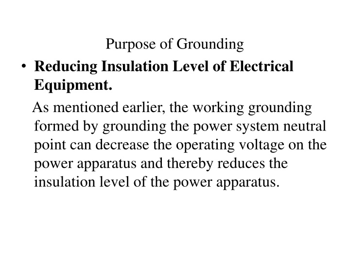
Purpose of Grounding Reducing Insulation Level of Electrical Equipment. As mentioned earlier, the working grounding formed by grounding the power system neutral point can decrease the operating voltage on the power apparatus and thereby reduces the insulation level of the power apparatus.
Ensuring Safe Operation of Power System The grounding resistance of transmission line towers must be lower than a certain value to reduce the potential difference between the transmission tower top and the phase conductor. A value of less than 50% of the impulse flashover voltage of the insulator can guarantee the safe operation of transmission lines. If the grounding resistance is too large, it could possibly cause a tower top potential which is high enough to trigger an insulators string flashover and a power outage might happen. In addition, as mentioned before, lightning protection systems in substations, such as lightning rods, shielding wires and surge arresters, must be grounded to the grounding devices to discharge the lightning energy to the earth.
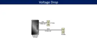
Detecting Ground Faults. In order to ensure personal and property safety, leakage breakers and other fault leakage protection devices are used in low-voltage circuits. If a ground fault happens at one point in the circuit, there must be a very large ground fault current to bring the protection device into action. In order to meet this condition, the neutral point on the secondary side of the step-down transformer should be grounded. In contrast, for a neutral point grounded circuit, if the enclosure of the electrical equipment is not grounded, when the electrical equipment enclosure is charged due to insulation damage or other reasons, the current generated in the circuit by the distributed capacitors cannot trigger the protection device, so the equipment enclosure should be grounded, as shown in Figure 4. The current I is:
Figure 4. Grounding of the enclosure of electrical equipment to ensure the protection device is triggered
Definition and Characteristics of Grounding Resistance Definition of Grounding Resistance Groundingresistance is the ratio between the potential of the grounding device and the current flowing into the earth through the grounding device, which is related to the soil characteristics and the size and shape of the grounding device.
The soil resistance encountered when a current flows into the soil is called the current- dispersing resistance. The grounding resistance consists of the ground lead resistance, the contact resistance between the ground lead and the grounding device, the resistance of grounding conductors themselves, the contact resistance between the grounding conductors and soil and the current-dispersing resistance of the soil.
Because the current-dispersing resistance is much greater than the other four kinds of resistance, the grounding resistance of a grounding device approximates to the current-dispersing resistance. Usually, the grounding resistance of a grounding device calculated by numerical methods or empirical formulas is the current-dispersing resistance of the soil, but the actually measured value is generally greater than the calculated result. This is because the actual contact between grounding conductors and the soil is not a complete surface-like contact, but a point-like contact.
as shown in Figure, the radius of a hemispherical grounding device is r0, the current flowing into the earth through the grounding device is I, assuming the terra firma is an homogenous soil
with resistivity of . The potential of the point with a distance r to the center of the hemispherical grounding device can be calculated by the potential formula of a point current source, which is: