R410A Gas-Insulated Transformer Design Study

In recent years, gas insulated transformers (GITs) have gained prominence for their reliability and efficiency. This study delves into the design criteria and modeling of R410A gas-insulated transformers to meet modern energy demands economically. Learn about the properties of R410A gas, the 3D modeling of a 50kVA transformer, and the safety features of this innovative technology.

Download Presentation

Please find below an Image/Link to download the presentation.
The content on the website is provided AS IS for your information and personal use only. It may not be sold, licensed, or shared on other websites without obtaining consent from the author.If you encounter any issues during the download, it is possible that the publisher has removed the file from their server.
You are allowed to download the files provided on this website for personal or commercial use, subject to the condition that they are used lawfully. All files are the property of their respective owners.
The content on the website is provided AS IS for your information and personal use only. It may not be sold, licensed, or shared on other websites without obtaining consent from the author.
E N D
Presentation Transcript
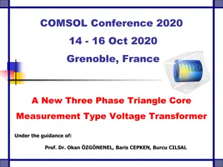
COMSOL Conference 2020 14 - 16 Oct 2020 Grenoble, France R410A GAS INSULATED DISTRIBUTION TRANSFORMER DESIGN Under the guidance of: Presented by: Dr. Okan ZG NENEL Professor Ezgi G NEY Prelector
Contents Introduction Definition of the R410A GIT Model Simulation Results Electrostatic Analysis Analysis Under Lightning Impulse Voltage Heat Analysis Conclusion References
Introduction In recent years, the gas insulating principle has been used in high-voltage equipment in terms of reliability, breakdown strength and working life. Gas insulated transformers (GITs) are widely used in underground and indoor substations in urban areas. This plays an even more important role in locating distribution transformers at the closest locations to the load (consumer points) for technical and economic reasons. In this study, the required design criteria of R410A gas insulated transformers will be achieved with the aim of meeting today s energy needs in an economical way.
What is R410A ? R410A is an azeotropic refrigerant mixture of equal parts of R32 and R125 that meets the needs of the industry in many new air conditioning systems. Since it does not contain chlorine, it is an environmentally friendly gas with zero ozone consumption coefficient. R410A gas has good potential in terms of Non-flammability CH2F2(Diflorometan) HF2C-CF3(Petraflorometan) Non-toxicity, No ODP, Low GWP, Note: Chlorine ions act as a catalyst and its availability in the market, and economical cause the ozone layer to become thinner by cost. converting ozone molecules into oxygen molecules.
3D Modeling of GIT in A real transformer model of 50 kVA, 34.5/0.4 kV is studied in this work. AutoCAD Environment The design is cylindrical in order to withstand high distribute the gas homogeneously. pressure and to 1. Tank 2. R410A Transformer core and windings are both insulated and cooled with R410A gas. 3. HV insulation 4. Dielectric Barrier 5. Tap Changer High voltage outputs are made through bushings. 6. Yokes 7. Bushing Insulators The tank is hermetic and safe to the touch. 8. Arc Sparking Gap 9. LV Bushing 10. Supporting Woods If for any reason an R410A gas leak occurs, the hazard is minimized as it is an inert gas and not flammable. Figure 2. R410A GIT of 50kVA for major details
The design of the tank and the cooling element are similar to oil-insulated transformer design. All the details are included for the model,such as tank, highvoltage (HV) and low voltage(LV) bushings, R410A, yokes, core, supporting woods, arc sparking gap, and tap changer on the HV side.
3D Modeling of GIT in AutoCAD Environment Electrostatic Analysis of 50 kVA GIT COMSOL Multiphysics 5.2a is used for computer simulations in this work. Four different materials are used to model the R410A GIT in the simulation environment. These are; wood with r 3, copper, soft iron, R410A with r 2.0. As the boundary condition, the peak value of the phase-earth voltage to the HV and LV windings is defined. Since the tank and yoke parts of the transformer are at ground potential, the earth boundary condition was chosen.
Simulation Results The most important step of this project is to obtain; tank pressure, heat effects , Breakdown curves at homogeneous and inhomogeneous electric fields on complex 3-D transformer models.
Electrostatic Analysis of 50 kVA GIT Line 1: Between the outer corner of the LV winding and the inner corner of the HV coil Line 2: Between the HV coil and the closest corner of the dielectric barrier Line 3: Between the HV coil and the closest corner of the yoke Figure 3. The lines (1,2 and 3) under electrostatic analysis.
In the figure, three critical lines are shown in red for Phase A windings, according to their importance level. The parts where the distances are the shortest are the outer corner of the low voltage winding and the inner corner of the high voltage winding. Also, the area between the high voltage winding and the yoke can be critical in terms of jumping.
Electrostatic Analysis of 50 kVA GIT Critical points in transformer windings have been determined in order to obtain the breakdown strength of R410A gas. Critical points If the potential distributions and electrical stress values at critical points are calculated, it will be possible to prevent partial discharges and possible failures.
Meshing Procedure The meshing procedure consists of tetrahedral elements for the analyzed models. A meshing procedure with small elements has been applied to the regions where electric field concentrates in models. In order to reduce the computation time, the network of the sections that are not very critical in terms of space is divided into a less frequent network, the critical areas such as windings and gas insulation sections are divided into a Figure 3. Figure 1. 50 kVA, 34.5/0.4 kV R410A gas-insulated distribution transformer, a) general view, b) meshed view much more dense network.
Electrostatic Analysis of 50 kVA GIT 60 point1 point2 point3 50 40 Volts in kV 30 20 10 0 0 10 20 30 40 50 60 70 arc length - mm Figure 4. Voltage levels at points 1, 2 and 3 according to arc length for phase A Line 1: between LV - HV winding Line 2: HV - dielectric barrier Line 3: HV - between the yoke
The breaking voltages and electric field strengths between these three lines are calculated using electrostatic solutions.
Electrostatic Analysis of 50 kVA GIT ? 100 90 Edmax Simulated Ed 80 70 The value of simulated electric fields for Figures 5 7 is below the Edmax curve. For Figure5, the value of the simulated electric field (125.05 kV/cm) is under the Edmax curve at 231 atm cm. At this point, SF6 gas pressure is equal to 1.59 atm inside the tank. Therefore, any SF6 gas pressure inside the tank above the Edmax curve is desirable. For instance, if SF6 gas pressure is selected at 1.59 atm (231 atm cm), the breakdown voltage will be 191.05 kV, which is much more than the peak value of lightning overvoltage (170 kV). Ed - kV/cm 60 50 40 30 20 0 100 200 300 400 500 600 p x d - ATM.cm Figure 5. Simulated electric field for point 1 for Phase A
Analysis under lightning impulse voltage for 50-kVA R410A GIT In this particular example, it is assumed that Phase B is exposed to lightning over voltages during the normal operating condition as seen in Figure 6. Figure 7 shows the electric potentials of all the windings at the time of peak voltages. Figure 6. Transformer under lightning voltage during normal operation (according to IEC 660076-3) Figure 7. Surface graph of peak electric potentials during lightning impulse
Heat Analysis of 50kVA Distribution Transformer Thermal analysis is required for transformers under nominal load to identify the location of the maximum temperature in the tank. Low voltage (LV) windings are assumed to operate at nominal load (50kVA with 0.9 power factor) and modeled as heat sources. Since the LV windings are heated with full load current, the heat generated is transported to the environment through conduction, convection and radiation. Figure 9. Temperature distribution (hot points) inside the tank. (a) 2D and (b) 2D axial symmetry analysis
As a result of the analysis, the maximum temperatures in the tank were calculated as 72.06 for 2D analysis and 76.34 for 2D axial symmetry analysis.
Conclusion This work handles the opportunity of gas-insulated distribution transformers in the theoretical study describing the flow behavior of fluids (R410A, air and transformer oil). In this study, the potential and electric field distribution of a three-phase transformer with R410A gas insulation was investigated using the finite element method. In the time-dependent analysis, firstly, three-phase gas insulated transformer was modeled in 3-D in its real dimensions, transformer materials and boundary conditions were defined.
Conclusion Electrostatic analysis is performed on 3-D models, whereas the heat analysis is achieved on the 2-D models due to heavy computational burden. According to the results of the analysis, it has been observed that the electric field values are at levels that will not create an excessive strain on the transformer in the operating voltage of this transformer. The computer simulations presented by the authors are believed to give accurate estimations with a reasonable accuracy and will be pioneers for the real time implementations to optimize the transformer design with respect to hot spots.
References 1. O. Ozgonenel, D. Thomas, Modeling and simulation of 2.5 MVA SF6-gas insulated transformer, Turkish Journal of Electrical Engineering & Computer Sciences, pp. 3475-3485 (2017) 2. IEEE. IEEE. Guide for Loading Mineral-Oil Immersed Transformers. IEEE Std. C57.91-1995. New York, NY, USA: IEEE, 1995. 3. P. 3. P. Bolin, H. Koch, Introduction and applications of gas insulated substation (GIS). In: IEEE Power Engineering Society General Meeting, San Francisco, CA, USA. New York, NY, USA: IEEE, pp. 920-926 (2005) 4. E. A. Mackenzie, J. Crossey, A. De Pablo, W. Ferguson, Online monitoring and diagnostics for power transformers, Electrical insulation (ISET) conference record of the 2010 IEEE international symposium, pp. 1-5 (2010) 5. B. Khan, J. Saleem, F. Khan, G. Faraz, R. Ahmad, N. U. Rehman, Z. Ahmad, Analysis of the dielectric properties of R410A Gas as an alternative to SF6 for high-voltage applications, High Voltage, pp. 41-48 (2018)
References 6. F. E. Brito, A. N. Gurova, U. V. Mardolcar, C. N. De Castro, Dielectric constant of the nearly azeotropic mixture R410A, International Journal of Thermophysics, pp. 415-427 (2000) 7. C. Meurer, G. Pietsch, M. Haacke, Electrical properties of CFC-and HCFC-substitutes, International Journal of Refrigeration, 24(2), 171-175 (2001) 8. X. Chen, J. Yang, C. Liu, J. Chen, Heating performance comparison of R410A and its substitutions in air-to-water heat pumps with vapor injection, International Journal of Refrigeration, pp. 78-87 (2018) 9. B. Khan, J. Saleem, F.Khan, G. Faraz, N. U. Rehman, Finite Element Analysis of Electric Field Distribution in the Dielectric Gas R410A as an Alternative to SF 6 for High Voltage Applications, In 2018 International Conference on Applied and Engineering Mathematics (ICAEM) IEEE, pp. 1-6 (2018) 10. K. M. Takami, H. Gholnejad, J. Mahmoudi, Thermal and hot spot evaluation on oil immersed power transformers by FEMLAB and MATLAB software s, In 2007 International Conference on Thermal, Mechanical and Multi-Physics Simulation Experiments in Microelectronics and Micro-Systems. EuroSime, IEEE, pp. 1-6 (2007)
Thank you Okan ZG NENEL Engineering Faculty Ezgi G NEY Vocational High School Department of Electrical and Energy Sinop University Sinop, Turkey eguney@sinop.edu.tr Department of Electrical and Electronic Engineering Ondokuz May s University Samsun, Turkey okanoz@samsun.edu.tr