RC Filter Circuits in Electronics
Learn about the relationship between time interval and charging current in half-wave rectified signals. Explore how RC filter circuits can reduce ripple across capacitors and improve power supply efficiency using zener diodes.

Download Presentation

Please find below an Image/Link to download the presentation.
The content on the website is provided AS IS for your information and personal use only. It may not be sold, licensed, or shared on other websites without obtaining consent from the author. If you encounter any issues during the download, it is possible that the publisher has removed the file from their server.
You are allowed to download the files provided on this website for personal or commercial use, subject to the condition that they are used lawfully. All files are the property of their respective owners.
The content on the website is provided AS IS for your information and personal use only. It may not be sold, licensed, or shared on other websites without obtaining consent from the author.
E N D
Presentation Transcript
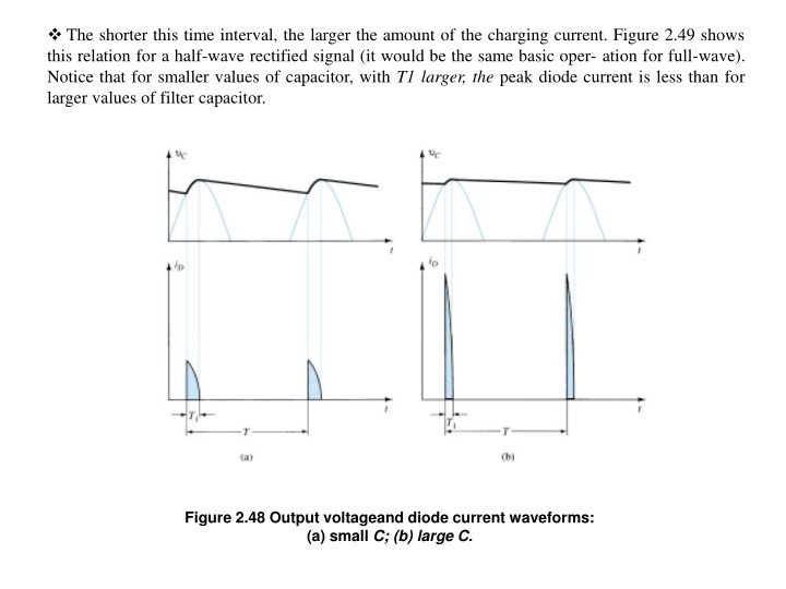
The shorter this time interval, the larger the amount of the charging current. Figure 2.49 shows this relation for a half-wave rectified signal (it would be the same basic oper- ation for full-wave). Notice that for smaller values of capacitor, with T1 larger, the peak diode current is less than for larger values of filter capacitor. Figure 2.48 Output voltageand diode current waveforms: (a) small C; (b) large C.
Since the average current drawn from the supply must equal the average diode current during the charging period, the following relation can be used (assuming constant diode current during charge time): The charging period, or we can say: Qdischarge = Qcharge (Q: charge of capacitor) ( 2 30) 12.4 RC FILTER: It is possible to further reduce the amount of ripple across a filter capacitor by using an additional RC filter section as shown in Fig. 19.8. The purpose of the added RC section is to pass most of the dc component while attenuating (reducing) as much of Figure 2.49 RC filter stage.
The ac component as possible. Figure 2.50 shows a full-wave rectifier with capacitor filter followed by an RC filter section. The operation of the filter circuit can be analyzed using superposition for the dc and ac components of signal. Figure 2.50 Full-wave rectifier and RC filter circuit.
(2 41) (2 42) As C is large in F, f = 100Hz so XC XC2 //RL for C= 100 F and XC R XC = 1/2 fc = 1/ 2 * 0.0001*100 = 100/ 2 = 15.9 Finally how to get a power supply circuit using zener diode of Vz=6V.
Fig. 2.49 And we can use IC voltage regulator, such as three terminal voltage regulator such as the series 78 regulators. Figure 2.50 5-V power supply.


")