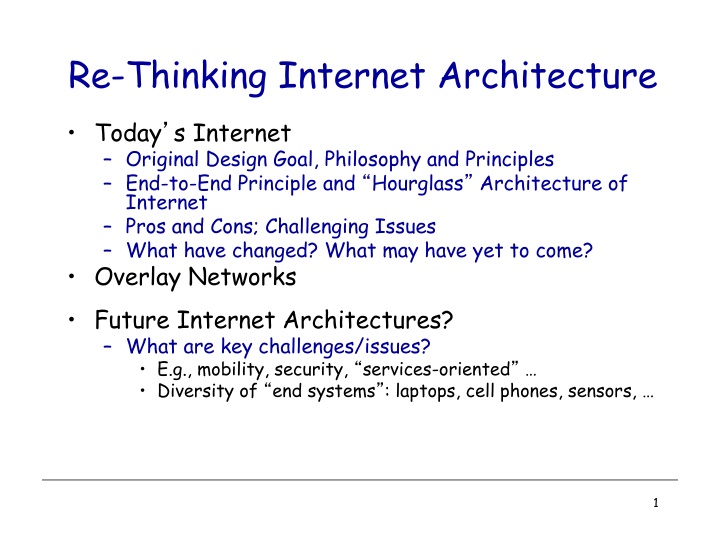
Re-Thinking Internet Architecture
Today's internet architecture faces evolving challenges and opportunities. Explore the original design goals, principles, and the shift towards future architectures like overlay networks. Dive into key issues such as mobility, security, and the diverse landscape of end systems. Discover architectural principles, design/implementations, and the enduring goals that shaped the internet we navigate today.

Download Presentation

Please find below an Image/Link to download the presentation.
The content on the website is provided AS IS for your information and personal use only. It may not be sold, licensed, or shared on other websites without obtaining consent from the author.If you encounter any issues during the download, it is possible that the publisher has removed the file from their server.
You are allowed to download the files provided on this website for personal or commercial use, subject to the condition that they are used lawfully. All files are the property of their respective owners.
The content on the website is provided AS IS for your information and personal use only. It may not be sold, licensed, or shared on other websites without obtaining consent from the author.
E N D
Presentation Transcript
Re-Thinking Internet Architecture Today s Internet Original Design Goal, Philosophy and Principles End-to-End Principle and Hourglass Architecture of Internet Pros and Cons; Challenging Issues What have changed? What may have yet to come? Overlay Networks Future Internet Architectures? What are key challenges/issues? E.g., mobility, security, services-oriented Diversity of end systems : laptops, cell phones, sensors, 1
Network Architecture What is (Network) Architecture? not the implementation itself design blueprint on how to organize implementations what interfaces are supported where functionality is implemented Two Basic Architectural Principles Modularity (e.g., layering) how to break network functionality into modules End-to-End Argument where to implement functionality 2
Architectural Principles (not unique to networks!) Zhi-Li s version (synthesized from various sources) End-to-end argument functionality placement Modularity Increase inter-operability and manage complexity vertical partition -> layered architecture horizontal partition? Keep it simple, stupid (KISS principle) Occam s Razor: choose simplest among many solutions! complicated design increases system coupling (inter- dependence), amplifies errors, .. don t over-optimize! Separating policies from mechanisms decouple control from data semantics-free Design for scale hierarchy, aggregation, 3
Some Design/Implementation Principles virtualization indirection soft state vs. hard state fate sharing randomization expose faults, don t suppress/ignore caching 4
Original Internet Design Goals [Clark 88] In order of importance: Connect existing networks initially ARPANET and ARPA packet radio network Survivability - ensure communication service even with network and router failures Support multiple types of services Must accommodate a variety of networks Allow distributed management Allow host attachment with a low level of effort Be cost effective Allow resource accountability 0 1. 2. 3. 4. 5. 6. 7. 5
Priorities The effects of the order of items in that list are still felt today E.g., resource accounting is a hard, current research topic Different ordering of priorities would make a different architecture! How well has today s Internet satisfied these goals? Let s look at them in detail 6
Summary: Internet Architecture Packet-switched datagram network IP is the compatibility layer Hourglass architecture All hosts and routers run IP Stateless architecture No per flow state inside network TCP UDP IP Satellite Ethernet ATM 7
Summary: Minimalist Approach Dumb network IP provide minimal functionalities to support connectivity Addressing, forwarding, routing Smart end system Transport layer or application performs more sophisticated functionalities Flow control, error control, congestion control Advantages Accommodate heterogeneous technologies (Ethernet, modem, satellite, wireless) Support diverse applications (telnet, ftp, Web, X windows) Decentralized network administration Beginning to show age Unclear what the solution will be probably IPv6? 8
Questions What priority order would a commercial design have? What would a commercially invented Internet look like? What goals are missing from this list? Which goals led to the success of the Internet? 9
Requirements for Todays Internet Some key requirements ( -ities ) Availability and reliability Always on , fault-tolerant, fast recovery from failures, Quality-of-service (QoS) for applications fast response time, adequate quality for VoIP, IPTV, etc. Scalability millions or more of users, devices, Mobility untethered access, mobile users, devices, Security (and Privacy?) protect against malicious attacks, accountability of user actions? Manageability configure, operate and manage networks trouble-shooting network problems Flexibility, Extensibility, Evolvability, ? ease of new service creation and deployment? evolvable to meet future needs? 10
Network Innovation? Internet has been a huge success! from research experiment to a global infrastructure minimalist Internet hourglass architecture dumb network: simple hop-by-hop best effort packet delivery smart and complexity at (programmable) end hosts: all kinds of applications enable innovations happen mostly end systems in terms of apps What about networks themselves? mostly closed equipment: software-&-hardware bundles, vendor-specific APIs slow protocol standardization process few can innovate: vendor controlled process 11
End System Based Overlay/P2P Services/Solutions General Concept of Overlays Some Examples End-System Multicast Rationale How to construct self-organizing overlay Performance in support conferencing applications Internet Indirection Infrastructure (i3) Motivation and Basic ideas Implementation Overview Applications 13
Overlay Networks Focus at the application level 15
Overlay Networks A logical network built on top of a physical network Overlay links are tunnels through the underlying network Many logical networks may coexist at once Over the same underlying network And providing its own particular service Nodes are often end hosts Acting as intermediate nodes that forward traffic Providing a service, such as access to files Who controls the nodes providing service? The party providing the service (e.g., Akamai) Distributed collection of end users (e.g., peer-to-peer) 16
Routing Overlays Alternative routing strategies No application-level processing at the overlay nodes Packet-delivery service with new routing strategies Incremental enhancements to IP IPv6 Multicast Mobility Security Revisiting where a function belongs End-system multicast: multicast distribution by end hosts Customized path selection Resilient Overlay Networks: robust packet delivery 17
IP Tunneling IP tunnel is a virtual point-to-point link Illusion of a direct link between two separated nodes F E A B tunnel Logical view: F E A B Physical view: Encapsulation of the packet inside an IP datagram Node B sends a packet to node E containing another packet as the payload 18
6Bone: Deploying IPv6 over IP4 F E A B tunnel Logical view: IPv6 IPv6 IPv6 IPv6 F E D A B C Physical view: IPv6 IPv6 IPv6 IPv6 IPv4 IPv4 Src:B Dest: E Src:B Dest: E Flow: X Src: A Dest: F Flow: X Src: A Dest: F Flow: X Src: A Dest: F Flow: X Src: A Dest: F data data data data A-to-B: IPv6 E-to-F: IPv6 B-to-C: IPv6 inside IPv4 B-to-C: IPv6 inside IPv4 19
MBone: IP Multicast Multicast Delivering the same data to many receivers Avoiding sending the same data many times unicast multicast IP multicast Special addressing, forwarding, and routing schemes Not widely deployed, so MBone tunneled between nodes 20
End-System Multicast IP multicast still is not widely deployed Technical and business challenges Should multicast be a network-layer service? Multicast tree of end hosts Allow end hosts to form their own multicast tree Hosts receiving the data help forward to others 21
RON: Resilient Overlay Networks Premise: by building application overlay network, can increase performance and reliability of routing Princeton Yale application-layer router Two-hop (application-level) Berkeley-to-Princeton route Berkeley 22
RON Can Outperform IP Routing IP routing does not adapt to congestion But RON can reroute when the direct path is congested IP routing is sometimes slow to converge But RON can quickly direct traffic through intermediary IP routing depends on AS routing policies But RON may pick paths that circumvent policies Then again, RON has its own overheads Packets go in and out at intermediate nodes Performance degradation, load on hosts, and financial cost Probing overhead to monitor the virtual links Limits RON to deployments with a small number of nodes 23
Secure Communication Over Insecure Links Encrypt packets at entry and decrypt at exit Eavesdropper cannot snoop the data or determine the real source and destination 24
Communicating With Mobile Users A mobile user changes locations frequently So, the IP address of the machine changes often The user wants applications to continue running So, the change in IP address needs to be hidden Solution: fixed gateway forwards packets Gateway has a fixed IP address and keeps track of the mobile s address changes www.cnn.com gateway 25
Unicast Emulation of Multicast Stanford Gatech CMU Berkeley End Systems Routers 26
IP Multicast Gatech Stanford CMU Berkeley Routers with multicast support No duplicate packets Highly efficient bandwidth usage Key Architectural Decision: Add support for multicast in IP layer 27
Key Concerns with IP Multicast Scalability with number of groups Routers maintain per-group state Analogous to per-flow state for QoS guarantees Aggregation of multicast addresses is complicated Supporting higher level functionality is difficult IP Multicast: best-effort multi-point delivery service End systems responsible for handling higher level functionality Reliability and congestion control for IP Multicast complicated Deployment is difficult and slow ISP s reluctant to turn on IP Multicast 28
End System Multicast CMU Stan1 Gatech Stanford Stan2 Berk1 Berkeley Berk2 Overlay Tree Stan 1 Gatech Stan2 CMU Berk1 Berk2 29
Potential Benefits Scalability Routers do not maintain per-group state End systems do, but they participate in very few groups Easier to deploy Potentially simplifies support for higher level functionality Leverage computation and storage of end systems For example, for buffering packets, transcoding, ACK aggregation Leverage solutions for unicast congestion control and reliability 30
Design Questions Is End System Multicast Feasible? Target applications with small and sparse groups How to Build Efficient Application-Layer Multicast Tree or Overlay Network? Narada: A distributed protocol for constructing efficient overlay trees among end systems Simulation and Internet evaluation results to demonstrate that Narada can achieve good performance 31
Performance Concerns Delay from CMU to Berk1 increases Stan1 Gatech Stan2 CMU Berk2 Berk1 Duplicate Packets: Bandwidth Wastage Gatech Stan1 Stan2 CMU Berk1 Berk2 32
What is an efficient overlay tree? The delay between the source and receivers is small Ideally, The number of redundant packets on any physical link is low Heuristic used: Every member in the tree has a small degree Degree chosen to reflect bandwidth of connection to Internet CMU CMU CMU Stan2 Stan2 Stan2 Stan1 Stan1 Stan1 Gatech Gatech Berk1 Berk1 Berk1 Gatech Berk2 Berk2 Berk2 Efficient overlay High latency High degree (unicast) 33
Why is self-organization hard? Dynamic changes in group membership Members may join and leave dynamically Members may die Limited knowledge of network conditions Members do not know delay to each other when they join Members probe each other to learn network related information Overlay must self-improve as more information available Dynamic changes in network conditions Delay between members may vary over time due to congestion 34
Performance Metrics Delay between members using Narada Stress, defined as the number of identical copies of a packet that traverse a physical link Delay from CMU to Berk1 increases Stan1 Gatech Stan2 CMU Berk1 Berk2 Stan1 Gatech Stress = 2 Stan2 Berk CMU 1 Berk2 35
ESM Conclusions Proposed in 1989, IP Multicast is not yet widely deployed Per-group state, control state complexity and scaling concerns Difficult to support higher layer functionality Difficult to deploy, and get ISP s to turn on IP Multicast Is IP the right layer for supporting multicast functionality? For small-sized groups, an end-system overlay approach is feasible has a low performance penalty compared to IP Multicast has the potential to simplify support for higher layer functionality allows for application-specific customizations 36
Internet Indirection Infrastructure (i3) Motivations Today s Internet is built around a unicast point- to-point communication abstraction: Send packet p from host A to host B This abstraction allows Internet to be highly scalable and efficient, but not appropriate for applications that require other communications primitives: Multicast Anycast Mobility 37
Why? Point-to-point communication implicitly assumes there is one sender and one receiver, and that they are placed at fixed and well- known locations E.g., a host identified by the IP address 128.32.xxx.xxx is located in Berkeley 38
IP Solutions Extend IP to support new communication primitives, e.g., Mobile IP IP multicast IP anycast Disadvantages: Difficult to implement while maintaining Internet s scalability (e.g., multicast) Require community wide consensus -- hard to achieve in practice 39
Application Level Solutions Implement the required functionality at the application level, e.g., Application level multicast (e.g., Narada, Overcast, Scattercast ) Application level mobility Disadvantages: Efficiency hard to achieve Redundancy: each application implements the same functionality over and over again No synergy: each application implements usually only one service; services hard to combine 40
Key Observation Virtually all previous proposals use indirection, e.g., Physical indirection point mobile IP Logical indirection point IP multicast Any problem in computer science can be solved by adding a layer of indirection 41
i3 Solution Build an efficient indirection layer on top of IP Use an overlay network to implement this layer Incrementally deployable; don t need to change IP Application Indir. layer TCP/UDP IP 42
Internet Indirection Infrastructure (i3): Basic Ideas Each packet is associated an identifier id To receive a packet with identifier id, receiver R maintains a trigger (id, R) into the overlay network data data id id Sender Receiver (R) data R trigger id R 43
Service Model API sendPacket(p); insertTrigger(t); removeTrigger(t) // optional Best-effort service model (like IP) Triggers periodically refreshed by end- hosts ID length: 256 bits 44
Mobility Host just needs to update its trigger as it moves from one subnet to another Receiver (R1) Sender id R1 id R2 Receiver (R2) 45
Multicast Receivers insert triggers with same identifier Can dynamically switch between multicast and unicast data data id id data R1 id R1 Receiver (R1) Sender id R2 data R2 Receiver (R2) 46
Anycast Use longest prefix matching instead of exact matching Prefix p: anycast group identifier Suffix si: encode application semantics, e.g., location Receiver (R1) data R1 data p|a data p|a p|s1R1 p|s2R2 p|s3R3 Sender Receiver (R2) Receiver (R3) 47
Service Composition: Sender Initiated Use a stack of IDs to encode sequence of operations to be performed on data path Advantages Don t need to configure path Load balancing and robustness easy to achieve Transcoder (T) data idT,id data idT,id data id Receiver (R) data R Sender T,id data id R idTT 48
Service Composition: Receiver Initiated Receiver can also specify the operations to be performed on data Firewall (F) data R data id data id F,R data Receiver (R) idFF Sender idF,R data id idF,R 49
Quick Implementation Overview i3 is implemented on top of Chord But can easily use CAN, Pastry, Tapestry, etc Each trigger t =(id, R) is stored on the node responsible for id Use Chord recursive routing to find best matching trigger for packet p = (id, data) 50


")