Readout Electronics for FPCCD VTX Development in 2014
Yasuhiro Sugimoto and Hisao Sato presented their research on readout electronics for FPCCD VTX in 2014. The study focused on R&D for a new interface board, clock drivers, and circuit design. They emphasized the importance of suppression of power consumption and dark current in achieving optimal performance for the 3-level clock driver. The presentation also covered the unique characteristics of inverted mode operation and H-clock with a 3-level driver. Additionally, the researchers discussed driver circuits, potential circuits utilizing specific components, and testing conducted at Shinshu University, including waveform analysis for different clock levels.

Download Presentation

Please find below an Image/Link to download the presentation.
The content on the website is provided AS IS for your information and personal use only. It may not be sold, licensed, or shared on other websites without obtaining consent from the author.If you encounter any issues during the download, it is possible that the publisher has removed the file from their server.
You are allowed to download the files provided on this website for personal or commercial use, subject to the condition that they are used lawfully. All files are the property of their respective owners.
The content on the website is provided AS IS for your information and personal use only. It may not be sold, licensed, or shared on other websites without obtaining consent from the author.
E N D
Presentation Transcript
Readout electronics for FPCCD VTX in 2014 Yasuhiro Sugimoto (KEK), Hisao Sato (Shinshu U.) 2014/12/18
R&D in 2014 3-level clock driver New interface board for 3-level clock drivers SEABAS2 board Clock drivers Interface board CCD/AFFROC Boards
3-level clock driver Suppression of power consumption Smaller pulse height is preferable: P=fCV2 Suppression of dark current Inverted mode (VL<~-7V) is preferable to suppress surface dark current In order to achieve these two contradictory requirements, 3-level clock for horizontal register is suitable
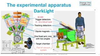
Inverted Mode In inverted mode, holes are collected near SiO2-Si interface Neutralize dark charge (electrons) of the interface states Drastic suppression of surface dark current Energy band structure of MIS structure SiO2 Gate n-Si Ec EF Ec EF Ec EF Ei Ei Ei Ev Ev Ev Vg=0 Vg<0 Vg<<0 Flat band Depletion (Normal) mode Inverted mode
H-clock with 3-level driver Use normal mode (VL>-7V) for H-shift Use inverted mode (VL<-7V) only once per line Thv Tpwv Tpwv Tovr Thc Thc P1V P2V,TG Tpwh P1H P2H,SG Tpwr RG Tv
Driver circuit Driver cards using discrete parts Pin-compatible with present driver cards, except for one pin which selects Normal/Inverted New interface board is also necessary to make use of 3-value function
Possible circuit 2.2uF 16V Driver IC EL7156 has tri- state output Use two EL7156 with different output pulse height (different VLand VH), and enable only one Even in tri-state, transistors in EL7156 become on if Vout>VHor Vout <VL Diodes are inserted in the VHand VLline Ringing in Vout has to be avoided because it causes voltage shift in Vout due to the diodes V+ U3 2.2uF 16V 330 2.2uF 16V D1 1M U1 D2 U5 VS+ OE In G VH Out VL VS- S/L Out VS+ OE In G VH Out VL VS- U6 In D3 U2 G V- U4 2.2uF 16V 2.2uF 16V 1M Rev.0 circuit diagram
Test at Shinshu Univ. 3 (4)-level waveform (V1H>V2H>0>V2L>V1L) has been obtained
V-clock with 3-level driver 3-value clock in V-clock might suppress spurious charge Takuya Imayoshi, Master Thesis
Status Sato-san has studied the driver circuit, and made some improvements We have ordered the 3-level driver cards to a company (GND) Design of new interface board is on-going (by Sato-san) will be ordered by the end of December and delivered by the end of FY2014