Reflector Antennas
High-gain reflector antennas play a crucial role in long-distance radio communications, radar systems, and radio astronomy. This guide covers the geometry, radiation mechanisms, and various types of reflector antennas like parabolic, Cassegrain, and Gregorian. Learn about designing these antennas for achieving gains above 30 dB and their historical significance from WW2.

Download Presentation

Please find below an Image/Link to download the presentation.
The content on the website is provided AS IS for your information and personal use only. It may not be sold, licensed, or shared on other websites without obtaining consent from the author.If you encounter any issues during the download, it is possible that the publisher has removed the file from their server.
You are allowed to download the files provided on this website for personal or commercial use, subject to the condition that they are used lawfully. All files are the property of their respective owners.
The content on the website is provided AS IS for your information and personal use only. It may not be sold, licensed, or shared on other websites without obtaining consent from the author.
E N D
Presentation Transcript
In the name of God Antenna and Microwave Laboratory Babol Noshirvani University of Technology, Iran Reflector Antennas Antenna and Microwave Laboratory Babol Noshirvani University of Technology zakeri@nit.ac.ir
Introduction: High-gain antennas are required for: long-distance radio communications (radio-relay links and satellite links), high-resolution radars, radio-astronomy, etc. Reflector systems are probably the most widely used high-gain antennas. easily achieve gains of above 30 dB designing such antenna systems was developed mainly during the days of WW2 when numerous radar applications evolved Antenna and Microwave Laboratory Babol Noshirvani University of Technology zakeri@nit.ac.ir
Introduction: reflector antenna consists of two components: a reflecting surface a much smaller feed antenna at the reflector s focal point The most common main reflector is the parabolic one Other common reflectors are: cylindrical, corner, and spherical. Antenna and Microwave Laboratory Babol Noshirvani University of Technology zakeri@nit.ac.ir
1. Geometry: D/2 zf zf = focal point O l1 F l2 directrix l1 = l2 The parabola is defined as the locus of a point that are equidistant from a focus and a directrix Antenna and Microwave Laboratory Babol Noshirvani University of Technology zakeri@nit.ac.ir
2. Radiation Mechanism: Type 1 : Prime-Focus Antenna Main Reflector: Parabolic Parabola has 2 valuable properties : 1) rays emanating from the focus are all reflected to parallel paths. 2) All paths from the focus to a plane transversal to the aperture at any distance, have the same length. Constructive phase Antenna and Microwave Laboratory Babol Noshirvani University of Technology zakeri@nit.ac.ir
Type 2 : Offset Reflector Antenna Main Reflector: Parabolic Antenna and Microwave Laboratory Babol Noshirvani University of Technology zakeri@nit.ac.ir
Type 3 : Cassegrain Antenna Main Reflector: Parabolic Subreflector: Hyperbolic Antenna and Microwave Laboratory Babol Noshirvani University of Technology zakeri@nit.ac.ir
Type 4 : Gregorian Antenna Main Reflector: Parabolic Subreflector: Elliptic Antenna and Microwave Laboratory Babol Noshirvani University of Technology zakeri@nit.ac.ir
Type 5 : Offset Cassegrain/Gregorian Antenna Antenna and Microwave Laboratory Babol Noshirvani University of Technology zakeri@nit.ac.ir
Type 6 : ADE (Axially Displaced Ellipse) Antenna Main Reflector: Parabolic Subreflector: Elliptic Antenna and Microwave Laboratory Babol Noshirvani University of Technology zakeri@nit.ac.ir
Type 7 : corner reflector antenna zakeri@nit.ac.ir 11 Antenna and Microwave Laboratory Babol Noshirvani University of Technology
3. Design Procedure: However, Antenna Laboratory of Babol Noshirvani University of Technology Proposes a Rule of Thumb Method So Let`s follow that Antenna and Microwave Laboratory Babol Noshirvani University of Technology zakeri@nit.ac.ir
3. Design Procedure: ???????????? ????? ?? = ????.???? ????????? A) Illumination Taper Illumination loss Spillover loss Ideal (uniform reflector) illumination practical (non-uniform reflector) illumination Antenna and Microwave Laboratory Babol Noshirvani University of Technology zakeri@nit.ac.ir
Different illumination taper values Illumination taper = 3dB Illumination taper = 6dB ???????????? ?????(??) =????.???? ????????? Illumination taper = 10dB Illumination taper = 20dB zakeri@nit.ac.ir 14 Antenna and Microwave Laboratory Babol Noshirvani University of Technology
3. Design Procedure: Step 1: illumination taper in Reflector Antenna should be somewhat between 10db to 15db. Step 2: Main dish diameter (D) is then calculated (in ) Antenna and Microwave Laboratory Babol Noshirvani University of Technology zakeri@nit.ac.ir
3. Design Procedure: fp Step 3: search the market for available Horn Antenna as the feed source. Remember that you can find only some standard pre-fixed antenna, not any size you like ! phi www.atmmicrowave.com D find the HPBW of Horn in its datasheet. Step 4: 1)set HPBW 2*phi 2) phi=Arctan[1/(2*(fp/D))] 3) fp is then calculated (in ). Step 5: check 0.25< fp/D <.65. if not, start again from step 1 with a different value. Antenna and Microwave Laboratory Babol Noshirvani University of Technology zakeri@nit.ac.ir
3. Design Procedure: x Step 5: now you can go to the mechanic to build your dish. However you need to give him the depth of the dish (x) rather than its focal point: ?2 16? ? = phi x is then calculated. D F Antenna and Microwave Laboratory Babol Noshirvani University of Technology zakeri@nit.ac.ir
4. Electromagnetic Properties: 1) Frequency Range: 300 MHz 100 GHz 2) Bandwidth: 5% 3) Pattern: Pencil beam, 25-50 dBi Gain, (1-10 deg HPBW) HPBW(experimental) 70* /D 4) Polarization: proportional to the Feed Antenna 5) In a fixed frequency, Larger Size of Dish yields to a greater gain. Antenna and Microwave Laboratory Babol Noshirvani University of Technology zakeri@nit.ac.ir
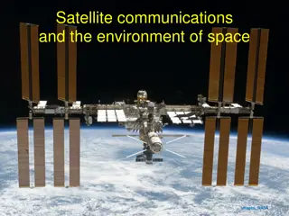
5. Applications: (visual review) Green Bank Telescope which stands near Green Bank, West Virginia The Very Large Array (VLA) at Socorro, New Mexico, United States for Radio Astronomy Applications Space Satellite Antenna Antenna and Microwave Laboratory Babol Noshirvani University of Technology zakeri@nit.ac.ir
5. Applications: (visual review) Reflector antenna used as radar in fighting ships Air Surveillance Radar at the airport IFF (identification of friend and foe) Reflector Radar Antenna and Microwave Laboratory Babol Noshirvani University of Technology zakeri@nit.ac.ir
5. Applications: (visual review) Arecibo Observatory is a radio telescope near city of Arecibo in Puerto Rico Its spherical reflector has a 305m dish in diameter. Surface is made of almost 40,000 perforated aluminum panels. Its focal point is 150m above reflector. These devices operate immersed in a liquid helium, to maintain a very low receiver temperature. Arecibo system operates at frequencies from 10MHz ( =30m) up to 50MHz ( =6m). 1MW planetary radar transmitter located in a special room inside dome. Antenna and Microwave Laboratory Babol Noshirvani University of Technology zakeri@nit.ac.ir
Now, Let`s get familiar with a brand new software: Antenna Magus Antenna and Microwave Laboratory Babol Noshirvani University of Technology zakeri@nit.ac.ir
Go to CST and simulate a example And complete the work sheet Antenna and Microwave Laboratory Babol Noshirvani University of Technology zakeri@nit.ac.ir
Reflector Antenna: Design Objectives for the Reflector Antenna set in Antenna Magus: 9.4 GHz 40 deg f0 Feed Antenna HPBW Reflector Antenna HPBW your desired (3-6 deg) zakeri@nit.ac.ir 24 Antenna and Microwave Laboratory Babol Noshirvani University of Technology
Lg= 8.7 mm Hg=10 mm Ha=30 mm F=160 mm D=400 mm Lf=30 mm Wg=23 mm Wa=52 mm S=160 mm zakeri@nit.ac.ir 25 Antenna and Microwave Laboratory Babol Noshirvani University of Technology
Reflector Antenna: zakeri@nit.ac.ir 26 Antenna and Microwave Laboratory Babol Noshirvani University of Technology
Worksheet Please complete the work sheet to your example: Frequency band : The figure of antenna in CST : The of size antenna in and in cm/mm : S11 : (set Z0=75 ohm) Zin (Re and Im) in CST : Surface Current (phase=0 deg) : linear 3D Power Pattern in CST : 2D Power Pattern for theory & CST : HPBW for theory & CST : Antenna and Microwave Laboratory Babol Noshirvani University of Technology zakeri@nit.ac.ir


 Antenna")


")
")
")