Regulation Techniques for Buffer Tank Level Control
"Learn about the use of averaging level control in regulating buffer tank levels to smooth out inflow variations. Explore tuning parameters, controller types, and examples of application in wastewater recovery facilities."

Uploaded on | 2 Views
Download Presentation

Please find below an Image/Link to download the presentation.
The content on the website is provided AS IS for your information and personal use only. It may not be sold, licensed, or shared on other websites without obtaining consent from the author. If you encounter any issues during the download, it is possible that the publisher has removed the file from their server.
You are allowed to download the files provided on this website for personal or commercial use, subject to the condition that they are used lawfully. All files are the property of their respective owners.
The content on the website is provided AS IS for your information and personal use only. It may not be sold, licensed, or shared on other websites without obtaining consent from the author.
E N D
Presentation Transcript
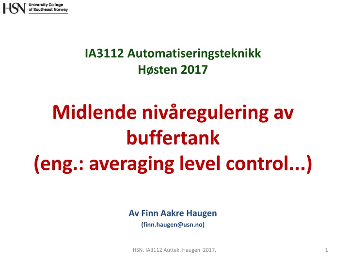
IA3112 Automatiseringsteknikk H sten 2017 Midlende niv regulering av buffertank (eng.: averaging level control...) Av Finn Aakre Haugen (finn.haugen@usn.no) HSN. IA3112 Auttek. Haugen. 2017. 1
2 Buffer tank with a level control system Aim: Averageing (or equalizing, or attenuating) inflow variations so that the outflow becomes smoother than the inflow. HSN. IA3112 Auttek. Haugen. 2017. 2
3 Example of application (results shown at end of this PPT): Level control of equalization magazine upstreams the VEAS water resource recovery facility (wrrf) or resource recovery facility (wrrf), at Slemmestad, south of Oslo, Norway: Pump (=aggregate of pumps) F_pump [L/s] F_net_in_internal_meas [L/s] Time-delay (transportation time), T_delay [d] F_in_unmeas [L/s] u_LC [L/s] = F_pump [L/s] V ker Tunnel Used in feedforward control F_tunnel [L/s] LC 1 A [m2] FT 1 Basin Level setpoint h_sp [m] F_V ker [L/s] Pump inlet h [m] LT 1 Note: Geometrical proportions are not real. HSN. IA3112 Auttek. Haugen. 2017. 3
4 How to tune LC? We need a sluggish or soft or compliant LC so that the liquid volume (the level) can take up the inflow variations. Ziegler-Nichols is useless here since it gives fast or stiff control :-( But Skogestad is excellent, using Tc as tuning parameter :-) Kc= 1/(Ki*Tc) Ti= 2*Tc where Ki= -1/A is the integrator gain or normalized process step response. How to select Tc? HSN. IA3112 Auttek. Haugen. 2017. 4
5 ... How to select Tc? As a start, assume P (proportional) level controller. It can be shown, from a mathematical model of the level control system, that hmax= (Tc/A)* Fin where hmaxis corresponding maximum allowed level change (in steady state) after max inflow step change, Fin. With a PI controller with the same Tc: hmax<= (Tc/A)* Fin Solving this inequality for Tc gives Tc >= A* hmax/ Fin => Specification of Tc in the PI settings: Tc = A* hmax/ Fin HSN. IA3112 Auttek. Haugen. 2017. 5
6 Comparison of responses in level h due to step change in inflow Fin, with P and with PI controllers: hmaks med PI-reg. hmaks med P-reg. HSN. IA3112 Auttek. Haugen. 2017. 6
7 Example Assumptions: A = 2000 m2 Fin= 1 m3/s hmax= 0.5 m Resulting Tc: Tc = A* hmax/ Fin= 2000*(-0.5)/(-1) = 1000 s PI settings: Kc= 1/(Ki*Tc) = -A/Tc= -2000 m2 / 1000 s = 2.0 (m3/s)/m Ti= 2*Tc= 2*1000 s = 2000 s HSN. IA3112 Auttek. Haugen. 2017. 7
8 Simulation! HSN. IA3112 Auttek. Haugen. 2017. 8
9 Results from VEAS: With original PI settings in the LC (Kc = 8.0 , Ti = 1000 s) With new (Skogestad) PI settings in the LC (Kc = 3.1 , Ti = 3240 s) Much smoother pump flow Pump flow 9 HSN. IA3112 Auttek. Haugen. 2017.