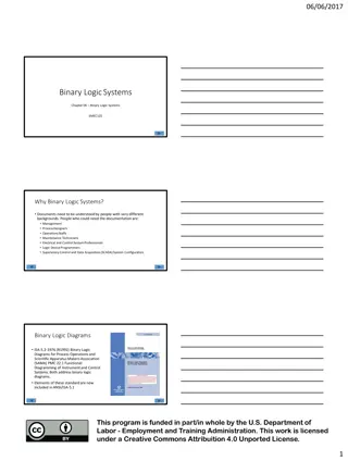
Learn about relay and pneumatic control logic in computer-controlled manufacturing systems. Explore topics such as relay specification, switch nomenclature, wire logic, and more. Get insights into designing and implementing control systems for efficient production processes.
Please find below an Image/Link to download the presentation.
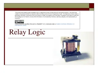
The content on the website is provided AS IS for your information and personal use only. It may not be sold, licensed, or shared on other websites without obtaining consent from the author. If you encounter any issues during the download, it is possible that the publisher has removed the file from their server.
You are allowed to download the files provided on this website for personal or commercial use, subject to the condition that they are used lawfully. All files are the property of their respective owners.
The content on the website is provided AS IS for your information and personal use only. It may not be sold, licensed, or shared on other websites without obtaining consent from the author.
E N D
Presentation Transcript
IENG 475 - Lecture 10 Relay and Pneumatic (Fluid) Control Logic 3/19/2025 IENG 475: Computer-Controlled Manufacturing Systems 1
Assignment Assignment Begin HW 04. Do this in teams of 1 2 persons. Turn in ONE scanned/digital PDF file with Subject Line: IENG 475 HW 04 and CC your partner (if any!) Select Project and Start Product Design Be ready to select a project by end of lab next week. Begin documentation of team project. Most of the routing information will be pulled from your MasterCAM files, and you can pull images from the SolidWorks files. Remember to collect timing data as you go! 3/19/2025 2 IENG 475: Computer-Controlled Manufacturing Systems
Relays (Switches) Specification: Poles & Throws Making (N.O.) / Breaking (N.C.) Latching (toggle) / Non-latching (momentary) Transfer between low power logic controls and high power energy controls Coil Nomenclature: relay power relay contactor starters (Overload protection, thermal) (< 10 A) (10 - 30 A) (> 30 A) Potential problem: contact bounce 3/19/2025 3 IENG 475: Computer-Controlled Manufacturing Systems
Switch Nomenclature Poles number of individual complete circuits switched at a time Throws number of positions for each pole Normally Open / Normally Closed stable position (if there is only one) Latching / Momentary stays in position / returns to normal position NC COM NO Single Pole, Double Throw, Latching Single Pole, Single Throw, Normally Closed, Momentary Single Pole, Single Throw, Normally Open, Latching SPDT Latching (Toggle) SPST - NO Latching SPST NC Momentary NC NO NC COM COM NO Double Pole, Single Throw, Normally Open, Latching Double Pole, Single Throw, Normally Open, Momentary Double Pole, Double Throw, Latching DPST - NO Latching DPST NO Momentary DPDT Latching (Toggle) 3/19/2025 4 IENG 475: Computer-Controlled Manufacturing Systems
Wire Logic Review: Current flows from source to ground AND ( ): c = a b a b c OR (+): c = a + b a c b NOT ( ): c = a a c 3/19/2025 5 IENG 475: Computer-Controlled Manufacturing Systems
Wire Logic Example: Missile engine (e) should start only when the President (a) orders it fired and both range officers (b and c) concur with the order. Once fired, the engine should stay on unless the self-destruct (d) is activated. e = [ ( a b c ) + e ] d e a b c d e 3/19/2025 6 IENG 475: Computer-Controlled Manufacturing Systems
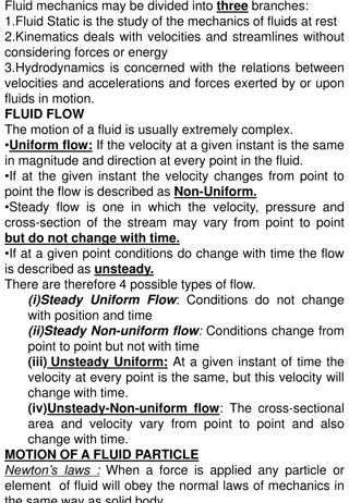
Pneumatics Why use Pneumatic Controls? Can withstand stalling without damage Explosion proof Generate little heat (at point of operation) No shock hazard Can operate underwater with minimal problems Can obtain high speeds Can obtain medium sized forces Switching Sense: Normally Not-Passing / Normally Passing Compare with N.O. / N.C. for electrical switching 3/19/2025 7 IENG 475: Computer-Controlled Manufacturing Systems
System View Components of a shop pneumatic system: compressor receiver main line branch line outlet 3/19/2025 8 IENG 475: Computer-Controlled Manufacturing Systems
ISO Symbology Air flow paths are shown as solid lines. Valve ports are shown on the outside of one of the position squares, denoting the normal position. Flow paths within the valves are shown as arrows. Terminations are shown as lines with a short cap line perpendicular to the end (T). Exhaust ports are shown as lines terminated with a outward pointing triangle. 3/19/2025 9 IENG 475: Computer-Controlled Manufacturing Systems
Signal / Control Valves Signal & Control Valves: Number of ports may be counted from the lines exiting the normal position square Number of squares is the number of positions Example: 3/2 manually actuated signal valve Function is evident by shifting position squares 3/19/2025 10 IENG 475: Computer-Controlled Manufacturing Systems
Valve Actuation General (Manual) Actuation Mechanical Actuation Solenoid Actuation Air Actuation 3/19/2025 11 IENG 475: Computer-Controlled Manufacturing Systems
Logic Valves (OR gate) Shuttle Valve (AND gate) Two Pressure Valve 3/19/2025 12 IENG 475: Computer-Controlled Manufacturing Systems
Single Acting Cylinder To extend the cylinder, air flows in the port side, compressing the spring side... To retract the cylinder, air flows out the port side, releasing the spring side. 3/19/2025 13 IENG 475: Computer-Controlled Manufacturing Systems
Double Acting Cylinder To extend the cylinder, air flows in the left side, exhausting the right side... To retract the cylinder, air enters on the right side, exhausting the left side. 3/19/2025 14 IENG 475: Computer-Controlled Manufacturing Systems
Speed Controls Two types: Manually Operated Operator controlled flow Needle Valves ISO Preferred Flow rate is set once* Closing a valve slows operation in BOTH directions! 3/19/2025 15 IENG 475: Computer-Controlled Manufacturing Systems
Miscellaneous Check Valve (a control valve): Permits flow in only one direction Pressure Sources: Compressor (fixed displacement shown) Must be running to generate pressure General Pressure Source Usually a Receiver 3/19/2025 16 IENG 475: Computer-Controlled Manufacturing Systems
ISO Pneumatic Diagrams From top to bottom, component layers are: Actuators Speed Controls Control Valves Logic Valves Signal Valves Pressure Supply 3/19/2025 17 IENG 475: Computer-Controlled Manufacturing Systems


")