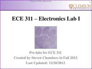
"Explore RLC resonant circuits, impedance variations, and electrical engineering humor. Learn about frequency impedance, circuit setups, and upcoming topics like Power Factor in AC circuits. Get ready to plot phasors and experiment with different circuit configurations!"
Please find below an Image/Link to download the presentation.
The content on the website is provided AS IS for your information and personal use only. It may not be sold, licensed, or shared on other websites without obtaining consent from the author. If you encounter any issues during the download, it is possible that the publisher has removed the file from their server.
You are allowed to download the files provided on this website for personal or commercial use, subject to the condition that they are used lawfully. All files are the property of their respective owners.
The content on the website is provided AS IS for your information and personal use only. It may not be sold, licensed, or shared on other websites without obtaining consent from the author.
Electrical Engineering puns !!!! Two antennas got married the wedding was lousy, but the reception was outstanding. Q: What did the electrical engineer say when he got shocked? A: That hertz.
Remember = 2 f radians/sec f = / 2 Cycles/sec (Hertz) Your calculations will be in radians per second but the signal generator is in cycles per second, Hertz
Setup your circuit and let me know right away if you suspect something is not what you expect. I want to help you early in the lab. Next week we will study Power Factor in AC electrical circuits More phasors to plot !!!


")