Rover CDR Team Presentation
In this presentation, the Rover CDR team outlines the mission objectives, system requirements, changes since PDR, system design concepts, and rocket design details. Team members present different sections with detailed visuals and summaries.

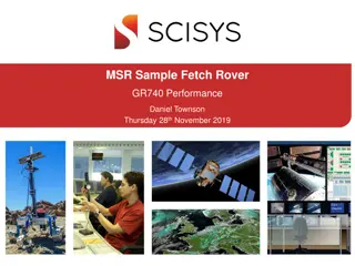
Download Presentation

Please find below an Image/Link to download the presentation.
The content on the website is provided AS IS for your information and personal use only. It may not be sold, licensed, or shared on other websites without obtaining consent from the author.If you encounter any issues during the download, it is possible that the publisher has removed the file from their server.
You are allowed to download the files provided on this website for personal or commercial use, subject to the condition that they are used lawfully. All files are the property of their respective owners.
The content on the website is provided AS IS for your information and personal use only. It may not be sold, licensed, or shared on other websites without obtaining consent from the author.
E N D
Presentation Transcript
Rover CDR Team Name Team Number 1
Presentation Outline Provide a simple outline of the presentation Indicate team member(s) who will present each section 2
Team Organization Single slide listing team members and roles Can use an organization chart 3
Acronyms Provide a list of acronyms used throughout the presentation Used as reference only. Does not need to be read through 4
System Overview Presenter name here 5
Mission Summary Overview of mission objectives Include any external objectives 6
System Requirement Summary Overview of system (mission) level requirements Use bullets or table to demonstrate understanding of requirements Include requirements for the rover Include requirements for the rocket 7
Changes since PDR Identify all changes since PDR in overall design 8
System Level Design Present selected overall design concept Configurations of rocket and rover This is a overview of the design concept 9
System Concept of Operations Provide overview of operations of the system from launch to landing to rover operations. Launch and descent operations Robot operations Post-launch recovery Simple flow diagrams and cartoons are a good way to present the CONOPS 10
Rocket Design Presenter Name 11
Rocket Changes since PDR Identify all changes to the rocket design 12
Overview of Rocket Describe overall rocket design A drawing of the rocket identifying all of its components and dimensions Length and diameter Identify major components and locations Nose cone Number of fins and size Location and size of rail buttons Location of avionics bay if using electronics deployment with altimeter(s) Total on the pad weight of the rocket with the primary and backup motors. This includes: All recovery harnesses and parachutes Primary or backup motor Rover 13
Design of Rocket (continued) Identify the rocket s stability. The center of gravity (CG) must be ahead of the center of pressure (CP) by at least one diameter (caliber) of your rocket. With primary motor With backup motor Motor retention method Friction fit is specifically disallowed Explain how the rover is stowed and deployed from rocket 14
Rocket Materials List of materials used: Airframe material Fin material Nose cone material Type of adhesives used Rail button source and material 15
Rocket Recovery System Parachute selection Size of and how determined Identify method for protecting parachute and rationale for choice Dual deploy? What is the expected descent rate(s) Harness Show drawing of recovery harnesses for each part of rocket Type of shock cord, lengths and strengths Identify linkages and load limits Attachment points, eyebolts, fender washers, etc. and their mounting methods 16
Rocket Recovery System Deployment Method Document method of initiating recovery Altimeter(s) Parachute release mechanism Motor ejection - specify motor delay in seconds for Primary motor Secondary motor Any rockets using VMAX motors must use an altimeter that deploys the parachutes as per Tripoli and NAR rules. 17
Rocket Recovery Electronics - if used Identify which commercial altimeter(s) will be used Show wiring diagram of altimeters with charges Document the number and size of the pressure ports for altimeter Document altimeter preparation steps. Specify the quantity of black powder to be used to separate each section Specify the volume of the section to be pressurized with calculated pressure level Document charge size testing and results Specify how sections are secured before the ejection charges separate sections friction fit shear pins - number and size Other Identify how charges are fired e-matches other 18
Altitude Recording Altimeter Identify the commercial altimeter to be used to officially record the rocket s altitude If using a commercial altimeter for deployment, it can be designated as the altitude recording altimeter 19
Rocket Motor Selection Identify primary motor selection Calculate thrust to on pad weight ratio using average thrust of the primary motor Thrust to weight ratio must be a minimum of 5:1 Identify back up motor selection and what changes to rocket would be required to successfully comply with contest rules Calculate thrust to on pad weight ratio using average thrust of the backup motor Thrust to weight ratio must be a minimum of 5:1 Include a simulation plot for the primary motor Include a simulation plot for the backup motor 20
Payload Design Overview Show diagram or picture of Payload Lander Identify major components Include dimensions 22
Payload Changes Since PDR Identify all design changes since PDR 23
Payload Lander Mechanics Mechanical design description of lander Structure Component placement How are components such as electronics secured to structure Material description Types of materials used 24
Lander Descent Control Design 25 ft/s Show final descent control design Identify size, color, shape, materials Identify mounting method 25
Lander Descent Control Design 10 ft/s Show final descent control design Indentify size, color shape Identify mounting method identify how it is released 26
Robotic Arm Design Show and explain robotic arm design Identify mechanisms used Describe how it operates 27
Robotic Arm End Effector Design Show and explain robotic arm end effector design Identify mechanisms used Describe how it holds and releases instrument package 28
Robotic Arm Stowage Show and explain how robotic arm is stowed during flight Identify mechanisms used Describe how it holds and releases arm 29
Camera Design Show and explain how camera is mounted and points to instrument package on the ground Show and describe mechanisms Explain how it works 30
Lander Mass Budget Show mass of all Mass of each structural element in grams Sources/uncertainties whether the masses are estimates, from data sheets, measured values, etc. Total mass of all components and structural elements Margin : The amount of mass (in grams) in which the mass budget meets, exceeds, or falls short of the mass requirement components of selected robot design 31
Payload Lander Electronics Block Diagram Show block diagram of electronics Identify processor, sensors, mechanism control circuits, radio, etc. 33
Lander Changes Since PDR Identify all design changes since PDR 34
Processor and Memory Processor and memory selection Include Processor speed and data width Data interfaces Memory storage requirements Boot time 35
Payload Sensors List sensors used in payload Include Type of sensors Manufacturer Power requirements Data interface 36
Camera Describe camera for capturing images 37
Lander Telemetry Radio Describe radio selected Type of radio Frequency Power level 38
Lander Telemetry Antenna Describe antenna Type antenna Antenna pattern 39
Lander Power Battery selection description Battery configuration (series/parallel/other) Power capacity Mounting method Protection circuits Short circuit Over-discharge for lithium ion cells 40
Lander Power Distribution Electrical Power System Design Show block diagram Power distribution to subsystems, mechanisms, actuators 41
Lander Power Budget List power consumption of all electrical components All values are to be in watt-hours Compare to capacity of battery in watt-hours Identify how long payload can operate on batteries 42
Software 43
Lander Software Changes Since PDR Identify all design changes since PDR 44
Lander Software Design Software development environment Flow Chart of software Identify software states and how software transitions to each state Power up Integration Launch Deployment Landing Ground operation Commanding 45
Software Development Plan Describe software tools used Describe software development process 46
Payload Lander Integration Describe design and construction of rocket section that will contain the payload Any mechanisms that interact with payload Describe how payload lander is configured for payload integration Describe process of payload integration 47
Ground Station Description Describe ground station design Show Block diagram How is command initiated. How is image captured. 48
Ground Station Radio Describe ground station radio selection Radio model frequency power 49
Ground Station Antenna Describe ground station antenna selection Model or custom made frequency radiation pattern gain 50


")