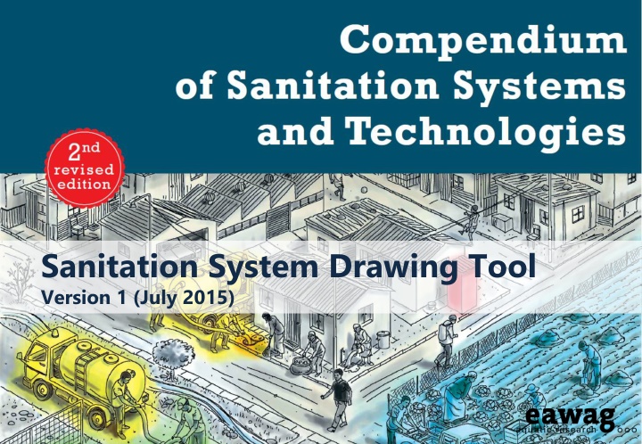
Sanitation System Drawing Tool Version 1 (July 2015)
This content provides information on the Sanitation System Drawing Tool Version 1 released in July 2015. It includes details about nine sanitation system templates and how they can be used to design a sanitation system. Each template represents different technology combinations for designing sanitation systems, offering flexibility to customize based on specific requirements. The content also emphasizes the importance of editing and modifying the templates to suit individual contexts. Images of the system templates and examples of different system configurations are provided.
Download Presentation

Please find below an Image/Link to download the presentation.
The content on the website is provided AS IS for your information and personal use only. It may not be sold, licensed, or shared on other websites without obtaining consent from the author.If you encounter any issues during the download, it is possible that the publisher has removed the file from their server.
You are allowed to download the files provided on this website for personal or commercial use, subject to the condition that they are used lawfully. All files are the property of their respective owners.
The content on the website is provided AS IS for your information and personal use only. It may not be sold, licensed, or shared on other websites without obtaining consent from the author.
E N D
Presentation Transcript
Sanitation System Drawing Tool Version 1 (July 2015)
Sanitation System Templates 1-9 The following slides show the nine sanitation system templates from the Compendium. A system template defines a suite of compatible and proven technology combinations from which a sanitation system can be designed. You can easily design your system by editing and modifying one of the templates. For example, remove the technology options that do not apply to your specific context. System 1: Single Pit System System 2: Waterless Pit System without Sludge Production System 3: Pour Flush Pit System without Sludge Production System 4: Waterless System with Urine Diversion System 5: Biogas System System 6: Blackwater Treatment System with Infiltration System 7: Blackwater Treatment System with Effluent Transport System 8: Blackwater Transport to (Semi-) Centralized Treatment System System 9: Sewerage System with Urine Diversion Edit the system templates by adding or removing elements, changing the position of elements, etc.
System 1: Single Pit System Fill and Cover / Arborloo Dry Cleansing Materials D.1 Settler Imhoff Tank ABR Anaerobic Filter WSP Aerated Pond FWS CW HSF CW VF CW Trickling Filter UASB Activated Sludge T.1 T.2 T.3 T.4 Filtration / Disinfection Urine Human-Powered Emptying and Transport C.2 Irrigation Fish Pond Plant Pond Disposal / Recharge D.6 D.9 D.10 D.11 Excreta U.1 Dry Toilet T.5 T.6 T.7 T.8 T.9 T.10 T.11 T.12 S.2 S.3 Single Pit Single VIP Effluent Sludge C.3 Motorized Emptying and Transport Pour Flush Toilet Blackwater U.4 Faeces POST Anal Cleansing Water Sedimen- tation / Thickening Unplanted Drying Beds Planted Drying Beds Co- Composting Biogas Reactor T.13 Pre-Treatment T.14 Application Surface Disposal and Storage D.5 D.12 Transfer Station T.15 Sludge C.7 Flushwater T.16 T.17 PRE Irrigation Soak Pit Disposal / Recharge D.6 D.7 D.11 Greywater Treatment Effluent Greywater D.11Disposal / Recharge Stormwater Stormwater Drains Disclaimer: This sanitation system was created using Eawag s Sanitation System Drawing Tool (Version 1). The user of this tool alone is responsible for the correctness and completeness of this system.
System 2: Waterless Pit System without Sludge Production S.4 S.5 Double VIP Fossa Alterna Faeces Pit Humus Human-Powered Emptying and Transport D.4 Application C.2 U.1 Dry Toilet Excreta Composting Chamber Compost Urine S.8 Organics Anal Cleansing Water Surface Disposal and Storage Dry Cleansing Materials D.12 Irrigation Soak Pit Disposal / Recharge D.6 D.7 D.11 Greywater Treatment Effluent Greywater D.11Disposal / Recharge Stormwater Stormwater Drains Disclaimer: This sanitation system was created using Eawag s Sanitation System Drawing Tool (Version 1). The user of this tool alone is responsible for the correctness and completeness of this system.
System 3: Pour Flush Pit System without Sludge Production Surface Disposal and Storage Dry Cleansing Materials D.12 Faeces Urine Application Surface Disposal and Storage D.4 D.12 Human-Powered Emptying and Transport Twin Pits for Pour Flush Pour Flush Toilet Pit Humus Blackwater S.6 U.4 C.2 Flushwater Anal Cleansing Water Irrigation Soak Pit Disposal / Recharge D.6 D.7 D.11 Greywater Treatment Effluent Greywater D.11Disposal / Recharge Stormwater Stormwater Drains Disclaimer: This sanitation system was created using Eawag s Sanitation System Drawing Tool (Version 1). The user of this tool alone is responsible for the correctness and completeness of this system.
System 4: Waterless System with Urine Diversion Surface Disposal and Storage Dry Cleansing Materials D.12 Anal Cleansing Water Anal Cleansing Water D.7 Soak Pit Application Surface Disposal and Storage D.3 D.12 Human-Powered Emptying and Transport Dehydration Vaults Faeces Faeces S.7 Dried Faeces C.2 Urine Diverting Dry Toilet Urinal U.2 U.3 Jerrycan / Tank Motorized Emptying and Transport C.1 Stored Urine D.2 Application Urine Urine S.1 Storage Tank C.3 Irrigation Soak Pit Disposal / Recharge D.6 D.7 D.11 Greywater Treatment Effluent Greywater D.11Disposal / Recharge Stormwater Stormwater Drains Disclaimer: This sanitation system was created using Eawag s Sanitation System Drawing Tool (Version 1). The user of this tool alone is responsible for the correctness and completeness of this system.
System 5: Biogas System D.11Disposal / Recharge Stormwater Stormwater Drains Irrigation Soak Pit Disposal / Recharge D.6 D.7 D.11 Greywater Treatment Effluent Greywater Organics D.13Biogas Combustion Biogas Pour Flush Toilet Biogas Reactor U.4 S.12 Faeces Blackwater Application Surface Disposal and Storage D.5 D.12 Sludge Urinal Urine Diverting Flush Toilet U.3 U.6 Urine Brownwater Flushwater Jerrycan / Tank Motorized Emptying and Transport C.1 Dry Cleansing Materials Urine S.1 Storage Tank D.2 Application Stored Urine C.3 Anal Cleansing Water D.7 Soak Pit Disclaimer: This sanitation system was created using Eawag s Sanitation System Drawing Tool (Version 1). The user of this tool alone is responsible for the correctness and completeness of this system.
System 6: Blackwater Treatment System with Infiltration D.11Disposal / Recharge Stormwater Stormwater Drains Soak Pit Leach Field D.7 D.8 Effluent Greywater Settler Imhoff Tank ABR Anaerobic Filter WSP Aerated Pond FWS CW HSF CW VF CW Trickling Filter UASB Activated Sludge T.1 T.2 T.3 T.4 Filtration / Disinfection Faeces T.5 T.6 T.7 T.8 T.9 T.10 T.11 T.12 Irrigation Fish Pond Plant Pond Disposal / Recharge D.6 D.9 D.10 D.11 Pour Flush Toilet Cistern Flush Toilet U.4 Septic Tank ABR Anaerobic Filter S.9 S.10 S.11 Blackwater Effluent U.5 Urine POST Human-Powered Emptying and Transport C.2 Flushwater Sedimen- tation / Thickening Unplanted Drying Beds Planted Drying Beds Co- Composting Biogas Reactor T.13 Sludge C.3 Motorized Emptying and Transport Pre-Treatment T.14 Application Surface Disposal and Storage D.5 D.12 Anal Cleansing Water T.15 Sludge T.16 Transfer Station C.7 T.17 PRE Surface Disposal and Storage Dry Cleansing Materials D.12 Disclaimer: This sanitation system was created using Eawag s Sanitation System Drawing Tool (Version 1). The user of this tool alone is responsible for the correctness and completeness of this system.
System 7: Blackwater Treatment System with Effluent Transport D.11Disposal / Recharge Stormwater Stormwater Drains Greywater Settler Imhoff Tank ABR Anaerobic Filter WSP Aerated Pond FWS CW HSF CW VF CW Trickling Filter UASB Activated Sludge T.1 T.2 T.3 T.4 Filtration / Disinfection Pre-Treatment Faeces T.5 T.6 T.7 T.8 T.9 T.10 T.11 T.12 Irrigation Fish Pond Plant Pond Disposal / Recharge D.6 D.9 D.10 D.11 Pour Flush Toilet Cistern Flush Toilet U.4 Septic Tank ABR Anaerobic Filter S.9 S.10 S.11 Simplified Sewer Solids-Free Sewer C.4 Blackwater Effluent Effluent U.5 C.5 Urine POST PRE Human-Powered Emptying and Transport C.2 Flushwater Sedimen- tation / Thickening Unplanted Drying Beds Planted Drying Beds Co- Composting Biogas Reactor T.13 Sludge C.3 Motorized Emptying and Transport Pre-Treatment T.14 Application Surface Disposal and Storage D.5 D.12 Anal Cleansing Water T.15 Sludge T.16 Transfer Station C.7 T.17 PRE Surface Disposal and Storage Dry Cleansing Materials D.12 Disclaimer: This sanitation system was created using Eawag s Sanitation System Drawing Tool (Version 1). The user of this tool alone is responsible for the correctness and completeness of this system.
System 8: Blackwater Transport to (Semi-) Centralized Treatment System D.11Disposal / Recharge Stormwater Stormwater Drains Greywater Settler Imhoff Tank ABR Anaerobic Filter WSP Aerated Pond FWS CW HSF CW VF CW Trickling Filter UASB Activated Sludge T.1 T.2 T.3 T.4 Filtration / Disinfection Pre-Treatment Faeces T.5 T.6 T.7 T.8 T.9 T.10 T.11 T.12 Irrigation Fish Pond Plant Pond Disposal / Recharge D.6 D.9 D.10 D.11 Pour Flush Toilet Cistern Flush Toilet U.4 Simplified Sewer Gravity Sewer C.4 Effluent Blackwater U.5 C.6 Urine POST PRE Flushwater Sedimen- tation / Thickening Unplanted Drying Beds Planted Drying Beds Co- Composting Biogas Reactor T.13 T.14 Application Surface Disposal and Storage D.5 D.12 Anal Cleansing Water T.15 Sludge T.16 T.17 Surface Disposal and Storage Dry Cleansing Materials D.12 Disclaimer: This sanitation system was created using Eawag s Sanitation System Drawing Tool (Version 1). The user of this tool alone is responsible for the correctness and completeness of this system.
System 9: Sewerage System with Urine Diversion D.11Disposal / Recharge Stormwater Stormwater Drains Greywater Settler Imhoff Tank ABR Anaerobic Filter WSP Aerated Pond FWS CW HSF CW VF CW Trickling Filter UASB Activated Sludge T.1 T.2 T.3 T.4 Filtration / Disinfection Pre-Treatment Faeces T.5 T.6 T.7 T.8 T.9 T.10 T.11 T.12 Irrigation Fish Pond Plant Pond Disposal / Recharge D.6 D.9 D.10 D.11 Urine- Diverting Flush Toilet Urinal U.6 Simplified Sewer Gravity Sewer C.4 Effluent Brownwater U.3 C.6 Urine POST PRE Flushwater Sedimen- tation / Thickening Unplanted Drying Beds Planted Drying Beds Co- Composting Biogas Reactor T.13 T.14 Application Surface Disposal and Storage D.5 D.12 Anal Cleansing Water T.15 Sludge T.16 Jerrycan / Tank Motorized Emptying and Transport C.1 T.17 C.3 Dry Cleansing Materials D.2 Application Stored Urine Urine S.1 Storage Tank Disclaimer: This sanitation system was created using Eawag s Sanitation System Drawing Tool (Version 1). The user of this tool alone is responsible for the correctness and completeness of this system.
How to Use the Sanitation System Drawing Tool This tool was prepared based on the 2nd edition of the Compendium of Sanitation Systems and Technologies. You can use it to: Draw your own system by copying / pasting ready-made graphical elements (i.e. products, technologies and arrows, see slides 4-6) to an empty template (slide 3) Edit and modify systems 1-9 from the Compendium by adding / removing elements, changing the position of elements, etc. (see slides 7-16) Print your tailor-made system, include it in a report or use the slide in a presentation Hints If you use your system in a PowerPoint presentation, you may want to add animations to your elements (e.g. to make them appear in sequence from User Interface to Use / Disposal). If you want to edit a technology box (e.g. in systems 1-9), it may be useful to ungroup the object first. Right-click the box and select Group -> Ungroup . Some hints for Windows users: To duplicate an element, press and hold the Ctrl key while dragging and dropping it with your mouse. Or simply hit Ctrl+D. You can move an element with your keyboard arrows. For smaller, more precise movements of an element, press and hold the Ctrl key while using the keyboard arrows.
Empty Template (Enter Title) Disclaimer: This sanitation system was created using Eawag s Sanitation System Drawing Tool (Version 1). The user of this tool alone is responsible for the correctness and completeness of this system.
Products For the design of a robust sanitation system, it is necessary to define all of the products that are flowing into (inputs) and out of (outputs) each of the sanitation technologies in the system. Anal Cleansing Water Dry Cleansing Materials Pit Humus Pre- Treatment Products Biogas Effluent Biomass Excreta Sludge Copy / paste the products you need to the input / output columns of your system template. Blackwater Faeces Stored Urine Brownwater Flushwater Stormwater Greywater Urine Compost Organics Dried Faeces
Sanitation Technologies Sedimen- tation / Thickening Fill and Cover / Arborloo D.13Biogas Combustion Greywater Treatment Jerrycan / Tank U.1 Dry Toilet S.1 Storage Tank T.1 Settler T.13 D.1 C.1 Urine- Diverting Dry Toilet Human-Powered Emptying and Transport T.14Unplanted Drying Beds U.2 S.2 Single Pit T.2 Imhoff Tank D.2 Application Stormwater Drains C.2 Motorized Emptying and Transport T.15Planted Drying Beds U.3 Urinal S.3 Single VIP T.3 ABR D.3 Application C.3 Pour Flush Toilet Simplified Sewer Anaerobic Filter T.16Co- U.4 S.4 Double VIP C.4 T.4 D.4 Application Composting Copy / paste the technologies you need to the corresponding functional group columns of your system template. The technology codes (e.g. U.1) refer to the technology information sheets in the Compendium. Cistern Flush Toilet T.17Biogas Reactor Solids-Free Sewer U.5 S.5 Fossa Alterna T.5 WSP D.5 Application C.5 Urine- Diverting Flush Toilet Twin Pits for Pour Flush Conventional Gravity Sewer U.6 S.6 T.6 Aerated Pond D.6 Irrigation C.6 Filtration / Disinfection Dehydration Vaults Transfer Station S.7 T.7 FWS CW D.7 Soak Pit C.7 Pre-Treatment Composting Chamber S.8 T.8 HSF CW D.8 Leach Field S.9 SepticTank T.9 VF CW D.9 Fish Pond POST PRE T.10Trickling Filter S.10 ABR D.10 Plant Pond Anaerobic Filter D.11Disposal / Recharge S.11 T.11 UASB Surface Disposal and Storage Biogas Reactor T.12Activated Sludge S.12 D.12
Arrows Bold arrows are used to show the most appropriate flow path. Thin arrows indicate alternative flow paths which are possible but not always common or recommended. Copy / paste arrows to your system template and create the link between products and / or technologies. To create a link between the source and destination boxes, pull the end / tip of the respective arrow. When you are close to the box, several red dots appear and you can use the appropriate red dot for connecting.
