Semiconductor Components and Their Functions
Semiconductor components like diodes and transistors are crucial in electronic circuits. Through the use of N-type and P-type materials, these components control the flow of current and provide functionalities such as rectification, amplification, and switching. Diodes allow current flow in one direction, while transistors act as current valves for signal control. Understanding the properties and functions of these components is essential in electronics.

Download Presentation

Please find below an Image/Link to download the presentation.
The content on the website is provided AS IS for your information and personal use only. It may not be sold, licensed, or shared on other websites without obtaining consent from the author.If you encounter any issues during the download, it is possible that the publisher has removed the file from their server.
You are allowed to download the files provided on this website for personal or commercial use, subject to the condition that they are used lawfully. All files are the property of their respective owners.
The content on the website is provided AS IS for your information and personal use only. It may not be sold, licensed, or shared on other websites without obtaining consent from the author.
E N D
Presentation Transcript
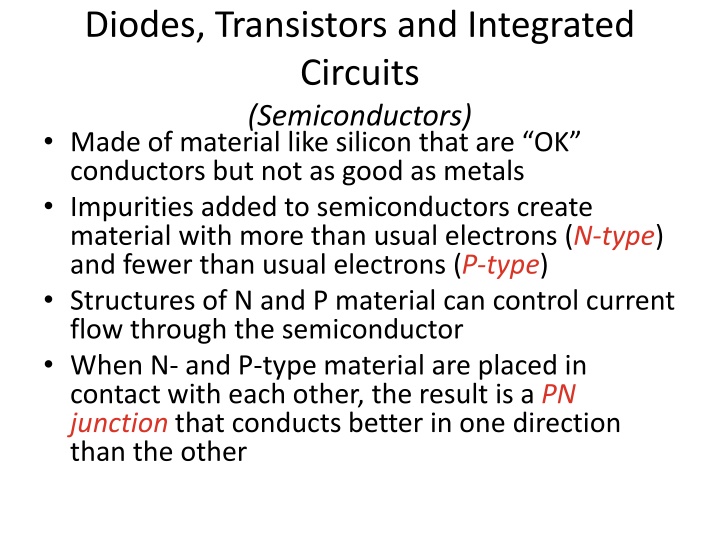
Diodes, Transistors and Integrated Circuits (Semiconductors) Made of material like silicon that are OK conductors but not as good as metals Impurities added to semiconductors create material with more than usual electrons (N-type) and fewer than usual electrons (P-type) Structures of N and P material can control current flow through the semiconductor When N- and P-type material are placed in contact with each other, the result is a PN junction that conducts better in one direction than the other
Diodes Allows current to flow in only one direction Two electrodes (Anode, Cathode) AC current is changed to varying pulses of DC (called rectification) Diodes used to change AC power to DC power are called rectifiers (heavy-duty diodes) Schematic Designator (D or CR) If AC voltage is applied to a diode, the result is a pulsing DC current because current is blocked when the voltage tries to push electrons in the wrong direction Anode Cathode Arrows indicate light (LED) Stripe on diode indicates CATHODE
Diodes (cont.) When current flows through a diode, a small positive voltage develops from the anode to the cathode Called forward voltage drop,usually less than 1 V Voltage depends on the type of diode and the materials it s made from Light-emitting diode or LED gives off light when current flows through it in the forward direction from anode to cathode Used as visual indicators (use less power than incandescent bulbs/lamps) Material from which the LED is made determines the color of light emitted
Transistors The function of a transistor is to control large signals with small ones An electronically controlled current valve When used as an amplifier, a transistor produces gain Transistors can also be used as a switch Schematic Designator (Q) Bipolar Junction Transistor (BJT) Field-Effect Transistor (FET)
Transistors (cont.) Two common types of transistors: bipolar junction transistors (BJT) and field effect transistors (FET) The Bipolar Junction Transistor (BJT) has three layers of N or P material connected to electrodes Depending on the arrangement of layers, a BJT is either an NPN or PNP transistor The three electrodes of an FET are the gate, drain, and source RF power transistors are used as the primary gain-producing component in RF power amplifiers Bipolar Junction Transistor Schematic (showing the 3 electrodes)
Transistors (cont.) The Field-Effect Transistor (FET) has a conducting path or channel of N and P material connected to the drain and source electrodes Voltage applied to the gate electrode controls current through the channel Drain Gate Source
Integrated Circuits An integrated circuit (IC or chip) is made of many components connected together as a useful circuit and packaged as a single component Schematic symbol Designator (IC or U) D Q CLK Q _ +
Which is true about forward voltage drop in a diode? A. It is lower in some diode types than in others B. It is proportional to peak inverse voltage C. It indicates that the diode is defective D. It has no impact on the voltage delivered to the load T6B01 A 3-10
What electronic component allows current to flow in only one direction? A. Resistor B. Fuse C. Diode D. Driven element T6B02 C 3-10
Which of these components can be used as an electronic switch? A. Varistor B. Potentiometer C. Transistor D. Thermistor T6B03 C 3-10
Which of the following components can consist of three regions of semiconductor material? A. Alternator B. Transistor C. Triode D. Pentagrid converter T6B04 B 3-10
What type of transistor has a gate, drain, and source? A. Varistor B. Field-effect C. Tesla-effect D. Bipolar junction T6B05 B 3-10
How is the cathode lead of a semiconductor diode often marked on the package? A. With the word cathode B. With a stripe C. With the letter C D. With the letter K T6B06 B 3-10
What causes a light-emitting diode (LED) to emit light? A. Forward current B. Reverse current C. Capacitively-coupled RF signal D. Inductively-coupled RF signal T6B07 A 3-10
What does the abbreviation FET stand for? A. Frequency Emission Transmitter B. Fast Electron Transistor C. Free Electron Transmitter D. Field Effect Transistor T6B08 D 3-10
What are the names for the electrodes of a diode? A. Plus and minus B. Source and drain C. Anode and cathode D. Gate and base T6B09 C 3-10
Which of the following can provide power gain? A. Transformer B. Transistor C. Reactor D. Resistor T6B10 B 3-11
What is the term that describes a devices ability to amplify a signal? A. Gain B. Forward resistance C. Forward voltage drop D. On resistance T6B11 A 3-11
What are the names of the electrodes of a bipolar junction transistor? A. Signal, bias, power B. Emitter, base, collector C. Input, output, supply D. Pole one, pole two, output T6B12 B 3-11
Which of the following devices or circuits changes an alternating current into a varying direct current signal? A. Transformer B. Rectifier C. Amplifier D. Reflector T6D01 B 3-11
Which of the following is commonly used as a visual indicator? A. LED B. FET C. Zener diode D. Bipolar transistor T6D07 A 3-11
What is the name of a device that combines several semiconductors and other components into one package? A. Transducer B. Multi-pole relay C. Integrated circuit D. Transformer T6D09 C 3-11
What is the function of component 2 in figure T-1? A. Give off light when current flows through it B. Supply electrical energy C. Control the flow of current D. Convert electrical energy into radio T6D10 C 3-11
Protective Components Protective components (such as fuses and circuit breakers) are used to prevent equipment damage or safety hazards such as fire or electrical shock Designed to remove power in case of a circuit overload Fuses blow one time protection Circuit breakers trip can be reset and reused Fuses interrupt current overloads by melting a short length of metal when the metal melts, the current path is broken and power is removed from circuits Replacing a fuse or circuit breaker with one with a higher current rating could allow the fault to
Circuit Breaker Schematics Ground Fault Circuit Interrupter (GFCI) circuit breaker Fuses
What electrical component is used to protect other circuit components from current overloads? A. Fuse B. Thyratron C. Varactor D. All these choices are correct T6A09 A 3-12
What is the purpose of a fuse in an electrical circuit? A. To prevent power supply ripple from damaging a component B. To remove power in case of overload C. To limit current to prevent shocks D. All these choices are correct T0A04 B 3-12
Why should a 5-ampere fuse never be replaced with a 20-ampere fuse? A. The larger fuse would be likely to blow because it is rated for higher current B. The power supply ripple would greatly increase C. Excessive current could cause a fire D. All these choices are correct T0A05 C 3-12
Circuit Gatekeepers Switches & Relays Switches and relays control current through a circuit by connecting and disconnecting paths for current to follow Switches and relays are described by their number of poles and the number of throws The combination of poles and throws describes the switch Each circuit controlled by the switch is a pole Each position is called a throw A switch is operated manually while a relay is a switch controlled by an electromagnet
Switch Configurations Switch SPS T SPDT es DPDT Pushbut ton Relay
Indicator, Meters and Displays Indicators and displays are important components for radio equipment An indicator is either ON or OFF A meter provides information as a value in the form of numbers or on a numeric scale A display combines indicators, numbers, and labels A liquid crystal display or LCD is used on the front panel of many radios and test instruments
What is the function of an SPDT switch? A. A single circuit is opened or closed B. Two circuits are opened or closed C. A single circuit is switched between one of two other circuits D. Two circuits are each switched between one of two other circuits T6A08 C 3-13
What type of switch is represented by component 3 in figure T-2? A. Single-pole single-throw B. Single-pole double-throw C. Double-pole single-throw D. Double-pole double-throw T6A12 A 3-13
What is a relay? A. An electrically-controlled switch B. A current controlled amplifier C. An inverting amplifier D. A pass transistor T6D02 A 3-13
Which of the following displays an electrical quantity as a numeric value? A. Potentiometer B. Transistor C. Meter D. Relay T6D04 C 3-14
Fig 3.15 Schematic Symbols (see text)
Fig 3.15 Schematic Symbols (cont., see text)
Schematic Diagrams and Symbols Symbols are used when drawing a circuit because there are so many types of components Schematic diagrams are a visual description of a circuit and its components that uses standardized drawings called circuit symbols Shows how the components are connected electrically
What is the name of an electrical wiring diagram that uses standard component symbols? A. Bill of materials B. Connector pinout C. Schematic D. Flow chart T6C01 C 3-14
What is component 1 in figure T-1? A. Resistor B. Transistor C. Battery D. Connector T6C02 A 3-14
What is component 2 in figure T-1? A. Resistor B. Transistor C. Indicator lamp D. Connector T6C03 B 3-14
What is component 3 in figure T-1? A. Resistor B. Transistor C. Lamp D. Ground symbol T6C04 C 3-14
What is component 4 in figure T-1? A. Resistor B. Transistor C. Ground symbol D. Battery T6C05 D 3-14
What is component 6 in figure T-2? A. Resistor B. Capacitor C. Regulator IC D. Transistor T6C06 B 3-14
What is component 8 in figure T-2? A. Resistor B. Inductor C. Regulator IC D. Light emitting diode T6C07 D 3-14
What is component 9 in figure T-2? A. Variable capacitor B. Variable inductor C. Variable resistor D. Variable transformer T6C08 C 3-14


")

")
")


 to")