Sequential Logic
Combinational circuits produce output based on input, while sequential circuits consider both input and previous state for output. Flip-flops store binary information and can switch states based on input signals. There are various types of flip-flops like Basic, Clocked RS, JK, D, T, Master-Slave, and Edge Triggering. Basic flip-flop circuits can be created using NAND gates or NOR gates. The cross-coupled connection in a flip-flop forms a feedback path, and they have outputs Q and Q', along with set and reset inputs.

Download Presentation

Please find below an Image/Link to download the presentation.
The content on the website is provided AS IS for your information and personal use only. It may not be sold, licensed, or shared on other websites without obtaining consent from the author.If you encounter any issues during the download, it is possible that the publisher has removed the file from their server.
You are allowed to download the files provided on this website for personal or commercial use, subject to the condition that they are used lawfully. All files are the property of their respective owners.
The content on the website is provided AS IS for your information and personal use only. It may not be sold, licensed, or shared on other websites without obtaining consent from the author.
E N D
Presentation Transcript
UNIT IV - Chapter 1 Sequential Logic
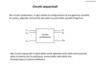
Combinational circuits:The output of a combinational circuit at any instant of time depends upon the input present at that time. Sequential circuits: The outputs in a sequential circuit are a function not only of external inputs but also of the present state of the memory elements (previous outputs).
There are two main types of sequential circuits: 1. Synchronous sequential circuit : A synchronous sequential circuit is a system whose behavior can be defined from the knowledge of its signals at discrete instants of time. 2. Asynchronous sequential circuit : An asynchronous sequential circuit s behavior depends upon the order in which its input signals change and can be affected at any instant of time.
FLIP FLOPS: Flip-flops are binary cells capable of storing one bit of information. A flip-flop circuit has two outputs, one for the normal value and one for the complement value of the bit stored in it. A flip-flop circuit can maintain a binary state indefinitely (as long as power is delivered to the circuit) until directed by an input signal to switch states.
The most common types of flip-flops are: 1. Basic flip flop 2. Clocked RS flip flop 3. JK flip flop 4. D flip flop 5. T flip flop 6. Master Slave flip flop 7. Edge Triggering flip flop
Basic Flip-Flop Circuit: Flip-flop circuit can be constructed from two NAND gates or two NOR gates.
The cross-coupled connection from the output of one gate to the input of the other gate constitutes a feedback path. Each flip-flop has two outputs, Q and Q', and two inputs, set and reset. This type of flip-flop is sometimes called a direct- coupled RS flip-flop or SR latch. The R and S are the first letters of the two input names.
b) Basic flip flop circuit using NAND gates: The NAND basic flip-flop circuit as shown in fig operates with both inputs normally at 1 unless the state of the flip-flop has to be changed. The application of a momentary 0 to the set input causes output Q to go to 1 and Q' to go to 0, thus putting the flip-flop into the set state. After the set input returns to 1, a momentary 0 to the reset input causes a transition to the clear state. When both inputs go to 0, both outputs go to 1- a condition avoided in normal flip-flop operation.
D Flip-Flop: The D flip-flop is a modification of the clocked RS flip-flop.
JK Flip-Flop: A JK flip-flop is a refinement of the RS flip-flop in that the indeterminate state of the RS type is defined in the JK type. Inputs J and K behave like inputs S and R to set and clear the flip-flop (note that in a JK flip-flop, the letter J is for set and the letter K is for clear).
T Flip-Flop: The T flip-flop is a modification of the clocked RS flip-flop.
TRIGGERING OF FLIP-FLOPS: The state of a flip-flop is switched by a momentary change in the input signal. This momentary change is called a trigger and the transition it causes is said to trigger the flip-flop. Clocked flip-flops are triggered by pulses. A pulse starts from an initial value of 0, goes momentarily to 1, and after a short time, returns to its initial 0 value.
The feedback path in a sequential circuits can produce instability if the o/p s of memory elements (flip-flops) are changing while the outputs of the combinational circuit that go to flip-flop inputs are being sampled by the clock pulse. This problem would be avoided by making flip flop to have a signal propagation delay from input to output in excess of the pulse duration. One way of achieving, the proper delay is to include within the flip-flop circuit a physical delay unit having a delay equal to or greater than the pulse duration.
To solve the feedback timing problem is to make the flip-flop sensitive to the pulse transition rather than the pulse duration. A clock pulse may be either positive or negative. A positive clock source remains at 0 during the interval between pulses and goes to 1 during the occurrence of a pulse. The pulse goes through two signal transitions: from 0 to 1 and the return from 1 to 0. As shown in Fig, the positive transition is defined as the positive edge and the negative transition as the negative edge. This definition applies also to negative pulses.
The clocked flip-flops are triggered during the positive edge of the pulse, and the state transition starts as soon as the pulse reaches the logic-1 level. The new state of the flip-flop may appear at the output, terminals while the input pulse is still 1. If the other inputs of the flip-flop change, while the clock is still 1, the flip-flop will start responding to these new values and a new output state may occur. When this happens, the output of one flip-flop cannot be applied to the inputs of another flip- flop when both are triggered by the same clock pulse.
Master-Slave Flip-Flop: A master-slave flip-flop is constructed from two separate flip-flops. One circuit serves as a master and the other as a slave, and the overall circuit is referred to as a master-slave flip-flop. The logic diagram of an RS master-slave flip-flop is shown in below Figure. It consists of a master flip- flop, a slave flip-flop, and an inverter. When clock pulse CP is 0, the output of the inverter is 1. Since the clock input of the slave is 1, the flip-flop is enabled and output Q is equal to Y, while Q' is equal to Y'. The master flip-flop is disabled because CP = 0.
When the pulse becomes 1, the information then at the external R and S inputs is transmitted to the master flip-flop. The slave flip-flop, however, is isolated as long as the pulse is at its 1 level, because the output of the inverter is 0. When the pulse returns to 0, the master flip-flop is isolated, which prevents the external inputs from affecting it. The slave flip-flop then goes to the same state as the master flip-flop.
The timing relationships shown in below Fig. illustrate the sequence of events that occur in a master-slave flip-flop. Assume that the flip-flop is in the clear state prior to the occurrence of a pulse, so that Y = 0 and Q = O. The input conditions are S = 1, R = 0, and the next clock pulse should change the flip-flop to the set state with Q = 1. During the pulse transition from 0 to 1, the master flip-flop is set and changes Y to 1. The slave flip-flop is not affected because its CP input is 0.
ANALYSIS OF CLOCKED SEQUENTIAL CIRCUITS: The behavior of a sequential circuit is determined from the inputs, the outputs, and the states of its flip flops. Both the outputs and the next state are a function of the inputs and the present state.
State table: The time sequence of outputs and flip flop states may enumerated are presented in a state table or transition table. The state table for the above circuit is shown below:
It consists of three sections present state, next state and output, the present state designates the states of flip flops before the occurrence of a CP. The next state shows the states of flip flops after the application of a CP. The output section lists out the values the output variables during the present states. The derivation of state table (ST) starts from and assumed initial state. In this case, we consider the initial state to be 00 (A=0, B=0).
State Diagram (SD): The state diagram is the graphical representation of information available in the state table. Each state is represented by a circle and the transition between states is indicated by directed lines connecting the circles. The state diagram of the sequential circuit above is shown below.
The binary number inside each circle identifies the state the circle represents. The direct lines are labeled with two binary numbers separated by a slash ( / ). The input value that causes the state transition is labeled first and then value of output during the present state after the /. For example: The directed line from 00 to 01 is labeled 1/0, meaning that the sequential circuit is in state 00 and when x=1 and on the termination of the next CP goes to next state 01.A directed line connecting a circle which itself indicates that no change of state occurs.
State Equations: A state equation (also known as an application equation) is an algebraic expression that specifies the conditions for a flip-flop state transition. The left side of the equation denotes the next state of a flip-flop and the right side, a Boolean function that specifies the present state conditions that make the next state equal to 1. A state equation is similar in form to a flip-flop characteristic equation, except that it specifies the next state conditions in terms of external input variables and other flip-flop values. The state equation for the Table 6-1 is expressed as follows:
The state equation for flip-flop A is simplified by means of a map as shown in following figure:
With some algebraic manipulation, the function can be expressed in the following form: which is the characteristic equation of an RS flip- flop.
The simplified form obtained in the map is manipulated algebraically, and the state equation obtained is:


 Basic flip flop circuit using NAND gates:")
 Basic flip flop circuit using NAND gates:")


:")