Simplifying Programming in Micro-processing Systems with Addressing Modes
Learn about the inherent, immediate, direct, relative, and indexed addressing modes in micro-processing systems to streamline programming in assembly language or machine code. Examples and illustrations included.

Download Presentation

Please find below an Image/Link to download the presentation.
The content on the website is provided AS IS for your information and personal use only. It may not be sold, licensed, or shared on other websites without obtaining consent from the author. If you encounter any issues during the download, it is possible that the publisher has removed the file from their server.
You are allowed to download the files provided on this website for personal or commercial use, subject to the condition that they are used lawfully. All files are the property of their respective owners.
The content on the website is provided AS IS for your information and personal use only. It may not be sold, licensed, or shared on other websites without obtaining consent from the author.
E N D
Presentation Transcript
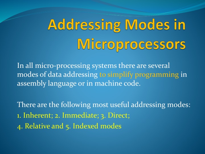
In all micro-processing systems there are several modes of data addressing to simplify programming in assembly language or in machine code. There are the following most useful addressing modes: 1. Inherent; 2. Immediate; 3. Direct; 4. Relative and 5. Indexed modes
Definition: Inherent addressing mode is the mode when instruction does not request any data because operation does not require that. EXAMPLES: 1. NOP No operation . This instruction is used only to pass the instruction execution cycle. It is used in assembly programming to adjust real-time program execution. 2. INX Increment Index register X
CPU MEMORY Address 100 PC = 100 INX INX 100 Address Bus Instruction Reg. Data Bus ALU 1000 Index Reg. X = 20FF 2100 PC content appears on the Address BUS = 100 Content of Memory in Address = 100 goes to Instruction Register in CPU over the Data Bus Op-Code [Increment X-Reg.] goes to ALU and content of X-reg. increments (20FF+1 = 2100)
Definition: Immediate addressing mode is the mode when instruction contains the operand (data) inside instruction word. Usually is used to store constants in the body of the program. EXAMPLE: 1. LDAA #55 ; Load digit 55 (0101 01010) to the Reg.A in CPU
CPU MEMORY Address 100 PC = 100 LDAA #55 LDAA #55 100 Address Bus Instruction Reg. Data Bus ALU 1000 Data Reg. A 55 PC content appears on the Address BUS = 100 Content of Memory in Address = 100 goes to Instruction Register in CPU over the Data Bus Op-Code [Load] goes to ALU and operand 55 is loaded from instruction to Reg.A in CPU
Definition: Direct addressing mode is the mode when instruction contains the address of data location. Direct addressing mode may have Extended Direct mode when operand is addressed in two consecutive bytes in the range of addresses from 0000 to FFFF EXAMPLES: 1. LDAA $1000 Load 8-bit data (e.g. 25) from the address $1000 to the register A . 2. LDX $2780 Load 16-bit data from addresses $2780 (low byte) and $2781 (high byte).
CPU MEMORY Address 1000 100 PC = 100 LDAA $1000 LDAA $1000 100 Address Bus Instruction Reg. Data Bus ALU 25 1000 Data Reg. A PC content appears on the Address BUS = 100 Content of Memory in Address = 100 goes to Instruction Register in CPU over the Data Bus Op-Code [Load] goes to ALU and address of the data [1000] appears on Address Bus The data [25] located in address [1000] goes to requested register A in CPU
Definition: Relative addressing mode is the mode when instruction include signed address offset and allows addressing memory location relative to existing (current) address. The offset can be 8 or 16 bit. EXAMPLE: Addr.| Instruction | Comment 0100 LDAA $1000 Load Reg.A from the address $1000 0103 INCA Increment Reg.A content 0104 BPL -4 Branch if plus to address = 0104 4= 0100
CPU 100 104 MEMORY LDAA $1000 INCA BPL -4 Address 100 103 104 PC = 104 PC = 100 LDAA $1000 Address Bus Instruction Reg. Data Bus BPL -4 ALU Data Reg. A 25 25 1000 PC content appears on the Address BUS = 104 Content of Memory in Address = 104 goes to Instruction Register in CPU over the Data Bus Op-Code [BPL=2A] goes to ALU and address of next instruction 104 04=100 goes to PC The new instruction address [100] is sent to the address bus and new instruction is loaded The new instruction LDAA $1000 is executed by loading Reg. A with data [25] from $1000
Definition: Indexed addressing mode is the mode when data address is calculated as sum of content of the index register and signed address offset in instruction. The offset can be: 5-bit (4 + 1 bit sign); 9 bit (8 + 1 bit sign) and 16 bit. EXAMPLE: Content of index register X = 1000 Addr.| Instruction | Comment 100 LDAA 20, X ; Load Reg. A from the address [X] + 20 104 STAA 40, X; Store Reg. A from the address [X] + 20
CPU 1040 104 1020 100 MEMORY LDAA 20,X LDAA 20, X Address 100 PC = 100 PC = 104 Address Bus Instruction Reg. STAA 40, X STAA 40, X 104 Data Bus ALU 25 25 1020 Data Reg. A 25 1040 PC content appears on the Address BUS = 100 Content of Memory in Address = 100 goes to Instruction Register in CPU over the Data Bus Op-Code [Load] goes to ALU and address of the data is calculated as [X=1000] + 20 = 1020 The data [25] located in address [1020] goes to requested register A in CPU PC content increments to next address = 104 The data [25] in Reg. A is stored in memory address [X=1000] +40 = 1040
Concepts of Programming on Assembly language: Microprocessor performs instructions encoded in machine core. This binary code is quite difficult for programmer . Thus, programming takes a lot of time Programmer prefer to write a program in form of text using symbolic language (text) and digits in their symbolic form (0,1,2, 9) Therefore, special program called Translator is needed to convert the textual form of the program to the machine code loadable to CPU for data execution 0100: 86 0101: 55 0102: bb 0103; 10 0104: 00 0105: 7a 0106: 11 0107: 00 1000: 25 1100: Begin Org $100 LDAA #55; ADDA $1000 STAA $1100 End Assembly Language Translator
Assembly Language Program Structure Assembly language consist of: 1. Directives, 2. Instructions and 3. Comments Definitions: Directive is a command to the translator which informs how to process subsequent assembly language instructions: e.g. Begin , End , Org , etc. Instruction is a command to the CPU which informs processor how to execute data or control information: e.g. LDAA #55; BPL -4, etc. Comment is text to programmer which explains the function of the instruction or group of instructions: e.g. Load of register A with initial value
Assembly Instruction Structure Assembly instruction consist of the following fields: Label Operation Operand(s) Comment Labels are symbols defined by programmer to identify memory locations and data areas of the assembly modules. The label is optional Operation is a field which specifies an assembler instruction, directive or a macro call: e.g. ADDA, LDAA, EQU, etc. Operand field is composed from one or more operands. This field is used to supply arguments to the assembly instruction, directive or macrofunction. Comment is optional text for programmer to explain what instruction or group of instructions does: e.g. Add 20 to content Reg. A and store result in Reg. A EXAMPLE Loop ADDA #$20 Add 20 to content of Reg. A
Standardized Flowchart Symbols Terminals: used to indicate start or end the program START Input / Output: used to indicate input or output data Load A Process: used to indicate data execution process Add A, B Condition: used to indicate condition after operation B>S? Connectors: used to indicate logic connection in program 1 2 Subroutine: used to indicate subroutine execution FIR
Arithmetic Functions Problem definition: Write a program to sum 3 data-elements located in memory from address $1000 and store the result in $1100 Flowchart Assembly program Start ORG $1500 ; Start from address 1500 [A] [1000] LDAA $1000 ; Load A from address [1000] [A] [A] + [$ 1001] ADDA $1001 ; Add A and [1001], store in A [A] [A] + [$ 1002] ADDA $1002 ; Add A and [1002], store in A [A] [$ 1010] STAA $1010 ; Store [A] in address 1010 End END ; End of the assembly program