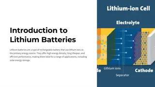
Solar System Equipment Specifications
The content outlines the required features and specifications for a solar energy system, including modules, inverters, and energy storage. It emphasizes labeling, UL listings, and compliance with safety standards for utility interconnection. The one-line diagram example provided illustrates key components and connections for illustrative purposes.

Download Presentation

Please find below an Image/Link to download the presentation.
The content on the website is provided AS IS for your information and personal use only. It may not be sold, licensed, or shared on other websites without obtaining consent from the author.If you encounter any issues during the download, it is possible that the publisher has removed the file from their server.
You are allowed to download the files provided on this website for personal or commercial use, subject to the condition that they are used lawfully. All files are the property of their respective owners.
The content on the website is provided AS IS for your information and personal use only. It may not be sold, licensed, or shared on other websites without obtaining consent from the author.
E N D
Presentation Transcript
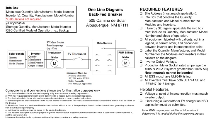
Info Box Module(s): Quantity, Manufacturer, Model Number Inverter(s): Quantity, Manufacturer, Model Number *Calculations not required. (If Applicable) Storage: Quantity, Manufacturer, Model Number CEC Certified Mode of Operation: i.e., Backup REQUIRED FEATURES Site Address (must match application). Info Box that contains the Quantity, Manufacturer, and Model Number for the Modules and Inverters. If Energy Storage is applicable the info box must include its Quantity, Manufacturer, Model Number and Mode of operation. All equipment labelled with callouts, not in a legend, in correct order, and disconnect between inverter and interconnection point. Label the Quantity, Manufacturer, and Model Number for the Modules and Inverters in their callouts on the diagram. Inverter Output Voltage. Production Meter Socket rated amperage (i.e 100A or 200A if system greater than 10kW AC) Note: neutrals cannot be bonded All ESS must have UL9540 listing. All Inverters must have both UL1741 SB and IEE1547-2018 listings. Helpful Features Voltage at point of Interconnection must match inverter output. If including a Generator or EV charger an NSD application must be submitted. One Line Diagram: Back-Fed Breaker 505 Camino de Solar Albuquerque, NM 87111 Components and connections shown are for illustrative purposes only 1. This illustrative sketch is not intended to specify utility interconnection or safety requirements. 2. PNM may request additional information if determined it is needed during the screening process. 3. This illustrative sketch is not intended to provide electrical design or code compliance directives. 4. Some components and connections shown may be internal to the inverter. The manufacturer and model number of the inverter must be shown on the drawing. 5. All switches, fuses, and mechanical interlock mechanisms which are part of the operating scheme to isolate the customers generating equipment from the utility during emergency or maintenance conditions must be shown on the single-line diagram. 6. The narrative description accompanying the single line interconnection diagram must contain sufficient detail to determine if the components in, and the operation of, the interconnection and protection systems meet the utility s interconnection and safety standards. Note: PNM may request additional information if determined it is needed during the screening process
REQUIRED FEATURES Site Address (must match application). Info Box that contains the Quantity, Manufacturer, and Model Number for the Modules and Inverters. If Energy Storage is applicable the info box must include its Quantity, Manufacturer, Model Number and Mode of operation. All equipment labelled with callouts, not in a legend, in correct order, and disconnect between inverter and interconnection point. Label the Quantity, Manufacturer, and Model Number for the Modules and Inverters in their callouts on the diagram. Inverter Output Voltage. All ESS must have UL9540 listing. All Inverters must have both UL1741 SB and IEE1547-2018. Production Meter is optional for systems sized 10 kW and under. Info Box Module(s): Quantity, Manufacturer, Model Number Inverter(s): Quantity, Manufacturer, Model Number *Calculations not required. (If Applicable) Storage: Quantity, Manufacturer, Model Number CEC Certified Mode of Operation: i.e., Backup One Line Diagram: Back-Fed Breaker For systems at or under 10kW AC 505 Camino de Solar Albuquerque, NM 87111 Helpful Features Voltage at point of Interconnection must match inverter output. If including a Generator or EV charger an NSD application must be submitted. Components and connections shown are for illustrative purposes only 1. This illustrative sketch is not intended to specify utility interconnection or safety requirements. 2. PNM may request additional information if determined it is needed during the screening process. 3. This illustrative sketch is not intended to provide electrical design or code compliance directives. 4. Some components and connections shown may be internal to the inverter. The manufacturer and model number of the inverter must be shown on the drawing. 5. All switches, fuses, and mechanical interlock mechanisms which are part of the operating scheme to isolate the customers generating equipment from the utility during emergency or maintenance conditions must be shown on the single-line diagram. 6. The narrative description accompanying the single line interconnection diagram must contain sufficient detail to determine if the components in, and the operation of, the interconnection and protection systems meet the utility s interconnection and safety standards. Note: PNM may request additional information if determined it is needed during the screening process
One Line Diagram: Line Side Tap 505 Camino de Solar Albuquerque, NM 87111 REQUIRED FEATURES Site Address (must match application). Info Box that contains the Quantity, Manufacturer, and Model Number for the Modules and Inverters. All equipment labelled with callouts, not in a legend, in correct order, and disconnect between inverter and interconnection point. Label the Quantity, Manufacturer, and Model Number for the Modules and Inverters in their callouts on the diagram. Inverter Output Voltage. Production Meter Socket rated amperage (i.e 100A or 200A if system greater than 10kW AC). Must be Fused and Service Entrance Rated. Note: Neutrals cannot be bonded. All Inverters must have both UL1741 SB and IEE1547-2018. Line side taps are not allowed with ESS systems. Production Meter is optional for systems sized 10 kW. Info Box Module(s): Quantity, Manufacturer, Model Number Inverter(s): Quantity, Manufacturer, Model Number *Calculations not required. *Line side taps not allowed with ESS systems Note: PNM may request additional information if determined it is needed during the screening process Components and connections shown are for illustrative purposes only 1. This illustrative sketch is not intended to specify utility interconnection or safety requirements. 2. PNM may request additional information if determined it is needed during the screening process. 3. This illustrative sketch is not intended to provide electrical design or code compliance directives. 4. Some components and connections shown may be internal to the inverter. The manufacturer and model number of the inverter must be shown on the drawing. 5. All switches, fuses, and mechanical interlock mechanisms which are part of the operating scheme to isolate the customers generating equipment from the utility during emergency or maintenance conditions must be shown on the single-line diagram. 6. The narrative description accompanying the single line interconnection diagram must contain sufficient detail to determine if the components in, and the operation of, the interconnection and protection systems meet the utility s interconnection and safety standards. Helpful Features Voltage at point of Interconnection must match inverter output If including a Generator or EV charger an NSD application must be submitted
One Line Diagram: Expansion REQUIRED FEATURES Site Address (must match application). Info Box that contains the Quantity, Manufacturer, and Model Number for the Modules and Inverters. If Energy Storage is applicable the info box must include its Quantity, Manufacturer, Model Number and Mode of operation. All equipment labelled with callouts, not in a legend, in correct order, and PV disconnect between inverter and interconnection point. Label the Quantity, Manufacturer, and Model Number for all Modules and Inverters including previously installed. For an Expansion, please clearly label the equipment as New or Existing. Please also make this distinction in the Info box. If V2G functionality is desired, EV charger must be depicted in diagrams and application. Inverter Output Voltage. Production Meter Socket rated amperage (i.e100A or 200A if system greater than 10kW AC) Note: neutrals cannot be bonded. All ESS must have UL9540 listing. All new Inverters (submitted on or after March 29, 2024) must have both UL1741 SB and IEE1547-2018. Helpful Features Voltage at point of Interconnection must match inverter output. If including a Generator or EV charger an NSD application must be submitted. Info Box Existing (E) Module(s): Quantity, Manufacturer, Model Number Inverter(s): Quantity, Manufacturer, Model Number New (N) Module(s) Quantity, Manufacturer, Model Number Inverter(s): Quantity, Manufacturer, Model Number *Calculations not required. *Line side taps not allowed with ESS systems (If Applicable) Storage (E) or (N): Quantity, Manufacturer, Model Number Mode of Operation: i.e., Backup 505 Camino de Solar Albuquerque, NM 87111 Note: PNM may request additional information if determined it is needed during the screening process
Additional Information For 3-phase systems Three Line Diagram is required. A Three-line diagram may be requested by reviewers as deemed necessary. For Large (>10 kW AC) and/or 3-phase systems: Please include reference to PNM Meter Standard Production meter Socket must be rated at least 200A For Battery Backup or Energy Storage Systems, please refer to PNM Interconnection --- --and Safety Standards as well. All diagrams are evaluated to ensure compliance with PNM metering and Interconnection and Safety Standards. This evaluation does not imply NEC compliance. For technical requirements for Interconnecting Distributed Energy Resources (DER) to -- --PNM s electric distribution system please see PNM s Technical Interconnection and ------ --Interoperability Requirements (TIIR). PNM Technical Interconnection and Interoperability Requirements