Solving Analysis Problems in Structural Engineering
Dive into the complexities of structural analysis, from preprocessing to postprocessing, exploring elements like correction, refinement, convergence, and more. Discover insights on stress, displacement, mesh refinement, and element mapping for improved results.

Uploaded on | 1 Views
Download Presentation

Please find below an Image/Link to download the presentation.
The content on the website is provided AS IS for your information and personal use only. It may not be sold, licensed, or shared on other websites without obtaining consent from the author. If you encounter any issues during the download, it is possible that the publisher has removed the file from their server.
You are allowed to download the files provided on this website for personal or commercial use, subject to the condition that they are used lawfully. All files are the property of their respective owners.
The content on the website is provided AS IS for your information and personal use only. It may not be sold, licensed, or shared on other websites without obtaining consent from the author.
E N D
Presentation Transcript
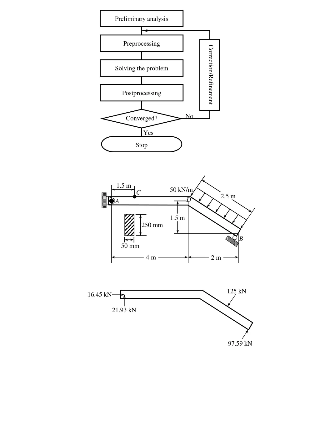
Preliminary analysis Preprocessing Correction/Refinement Solving the problem Postprocessing No Converged? Yes Stop 1.5 m 50 kN/m C 2.5 m D A 1.5 m 250 mm B 50 mm 4 m 2 m 125 kN 16.45 kN 21.93 kN 97.59 kN
x M 16.45 kN N V 21.93 kN h=.25 in 300 lb 300 lb 2.0 in .75 in
F 1 3 2 160o Rapid size change Missing element
1 6 4 E2 7 5 E1 E3 8 2 3 Beams Plane solids Shells 3D solids Stress or displacement Exact value Acceptable mesh size Need mesh refinement No. of elements Fix center node Plate Plate Rigid-bar elements Fix all nodes y 3 3 x 2 2 3 L 3 L 1 1 2 2 1 1 L L 1,000 N 1,000 N
b 0.25b 0.5b b min = 0.973 ave min = 0.668 ave min = 0.198 ave max = 1.027 ave max = 1.387 ave max = 2.575 ave C F d F Hole Force Plate Plate Bar elements pmax
Stress at integration point Stress Averaged nodal stress Elem 1 Elem 2 Elem 3
2 1-2-3 6 1 4 3 5 5 6 4 Mapped mesh Free mesh p p Symmetry plane p p Modeled portion y y p x p x
Plane solid element 1 F Frame element Plane solid element Plane solid element F 1 F Constraint 2 h Frame elements Frame elements 3 Plate 2 Plate 1 Plate 1 Plate 2 Nodal coupling Rigid element y x 1 m 1 m F2 = 240 N y 3 4 2 1 x 1 m 1 m
Input x (load, heat) Output y (displ, temp) y = ax y1 x1 x1 x2 x2 y2 y = ax 2x1 2y1 y 2x1 +3x2 2y1+3y2 Global Local Local Global Linear Linear Linear Strain Displacement Force Stress = E A0 A F/2 L L E L 0 F/2 (a) (b) (c) Load Stress time time
y (.5,1) (0,1) (1,1) 7 8 9 6 (1,.5) 4 5 (0,.4) (.4,.3) 1 2 3 x (0,0) (.5,0) (1,0) E = 100 Pa, = 0.25 y (0,1) (.5,1) (1,1) 8 9 7 (1,.5) (0,.4) 4 6 xx= 1 Pa 5 (.4,.3) 1 2 3 x (0,0) (.5,0) (1,0) 1 2 3 x 0.5 m 1.0 m
Stress at integration point Stress Averaged nodal stress 1 2 3 4 Elem 1 Elem 2 Elem 3 Stress or displacement Exact value Small change Large change Acceptable mesh size Need mesh refinement Nb Na No. of elements
350 mm 200 mm 400 mm 10 kN 20 mm 1 m 20 mm 10 kN 20 mm 10 mm 1 m 10 kN 20 mm 1 m 20 mm 1 m 1 m 1 kN 0.5 m 1 kN 1.3 m 1 kN 0.5 m 1 kN 1.3 m
y P x P P L 8 kN 400 mm 400 mm 400 mm 20 N/mm 400 mm 400 mm 400 mm Py Px Px y Py x 1 2 3 x 0.5 m 1.0 m
y (0,3) 1 (2,2.5) 2 (4,2) 3 (0,1) 4 5 6 (1,1) (4,1) (0,0) 8 7 9 (2,0) (4,0) x y x E = 100 Pa, = 0.25 y (0,1) (.5,1) (1,1) 8 9 7 (1,.5) (0,.4) 4 6 u = 0.01m 5 (.4,.4) 1 2 3 x (0,0) (.5,0) (1,0)
(a) 4-Node Quadrilateral Plane stress elements (b) 3-Node Triangular Plane stress elements (c) A single 2-Node Hermite beam element 16 15 12 11 14 p 7 8 10 6 4 3 2 1 5 9 13
Fall 2019 Qualifying exam figures P P P y P x 7 6 5 11 Q4 F 10 Q8 8 4 Q4 1 2 3 9 E = 100 Pa, = 0.25 y (0,1) (.5,1) (1,1) 8 9 7 (1,.5) (0,.4) 4 6 u = 0.01m 5 (.4,.4) 1 2 3 x (0,0) (.5,0) (1,0)


 4-Node Quadrilateral Plane stress elements")
