Solving the Light Bulb Puzzle with Three Switches
Consider a challenging puzzle where three light bulbs are controlled by three separate switches in a different room. You need to determine which switch controls each light, but you can only enter the room once. Dive into this intriguing problem and explore a creative solution! Start your design project on digital logic with a lateral thinking approach to tackle this puzzle effectively.

Download Presentation

Please find below an Image/Link to download the presentation.
The content on the website is provided AS IS for your information and personal use only. It may not be sold, licensed, or shared on other websites without obtaining consent from the author.If you encounter any issues during the download, it is possible that the publisher has removed the file from their server.
You are allowed to download the files provided on this website for personal or commercial use, subject to the condition that they are used lawfully. All files are the property of their respective owners.
The content on the website is provided AS IS for your information and personal use only. It may not be sold, licensed, or shared on other websites without obtaining consent from the author.
E N D
Presentation Transcript
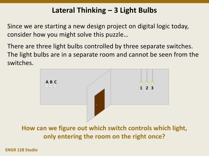
Lateral Thinking 3 Light Bulbs Since we are starting a new design project on digital logic today, consider how you might solve this puzzle There are three light bulbs controlled by three separate switches. The light bulbs are in a separate room and cannot be seen from the switches. A B C 1 2 3 How can we figure out which switch controls which light, only entering the room on the right once? ENGR 128 Studio
Design Studio Week 6 Today you will: Learn the requirements and constraints for Project 2 Review digital logic circuits Learn a technique for choosing a design from several options Discover tools for managing project teams Assignments: Exercise worksheet for digital circuit design Technical memo on project progress through conceptual design ENGR 128 Studio
Project 2 Ask Let s hear from our next customer: I need a digital logic circuit. Digital logic circuits combine digital inputs using Boolean functions, such as AND, OR, and NOT. While we re used to working with logic levels of TRUE and FALSE, or perhaps their binary counterpart of 1 and 0, real electrical circuits use two distinct voltage levels (such as 5 V and 0 V). The circuit you will need to make is being handed out to your team. ENGR 128 Studio
Concept Review - Digital Logic Circuits What does this circuit do? How do you even describe what it does? A B C D Truth table Equation Let s create a truth table and equation for this circuit. F ENGR 128 Studio
Determining a Digital Design Imagine Is there more than one way to construct a digital circuit? Yes a single truth table has multiple implementations Sum of products A B C G G = A B C + A B C + AB C + ABC 0 0 0 1 0 0 1 0 Product of sums G = (A+B+ C)(A+ B+C)(A+ B+ C)( A+B+ C) 0 1 0 0 0 1 1 0 Simplifying G = B C + AB 1 0 0 1 1 0 1 0 Creative manipulation 1 1 0 1 G = (B+C)AB 1 1 1 1 G = Is A B C? ENGR 128 Studio
Concept Scoring Pugh Matrix Plan How can we choose between different designs? One rigorous way is called the Pugh design matrix, which assigns ratings based on each concept s performance to selected criteria. Remember sometimes it s okay not too be rigorous. A design that interests you might just be the best choice! ENGR 128 Studio
Using the Design Matrix Approach Plan In general, the steps for creating and completing a design matrix are as follows: 1. Select the evaluation criteria (first column). 2. Assign weights to each criterion. 3. Place concepts to be evaluated in subsequent columns. 4. Rate each concept against the criteria, e.g. a range from 0 to 4. 5. Multiply each rating by the weight and sum the results. 6. The concept with the highest score wins. Let s create a design matrix for our four digital logic equations. ENGR 128 Studio
Problems with the Design Matrix Approach Plan The design matrix is might be the most common method of selecting solutions in engineering (especially for students). Beware of some of the following pitfalls: Avoid using requirements as evaluation criteria, which leads to requirements tradeoff. Your selected design should meet all of the requirements. The design matrix is often viewed as objective, but subjective selection of evaluation criteria, weights, and rating ranges has an enormous impact on the end scores. Try to include as much information as possible to fully evaluate the designs, but too many lesser criteria can outweigh one important factor. ENGR 128 Studio
Subsystems Plan Breaking large designs into smaller pieces has several benefits: Define smaller, solvable problems Complete designs in a reasonable and predictable time Easily assign parts of the design to different teams Most major engineering projects are not developed all at once; they are developed in pieces. Breaking a solution into manageable chunks, or subsystems, is an important part of engineering design: Requirements are allocated to different subsystems, making sure that each requirement is addressed by at least one subsystem Development of subsystems may be concurrent or sequential ENGR 128 Studio
Subsystem Example Vehicle Subsystems Consider the following problem with the given requirements: Transport families to nearby destinations safely and affordably. Requirements: Accommodate seating for at least 6 people. Reduce external impact force by more than 95% within the cabin. Operate at 35 mpg fuel efficiency or better in-city. Constraints: Gasoline-powered passenger vehicle Emissions standards, speed limits, roadway size, etc. ENGR 128 Studio
Subsystem Example Vehicle Subsystems (cont.) Subsystem Definition: Divide the development into two subassemblies: Body frame (and cabin interior) Accommodate seating for at least 6 people. Reduce external impact force by more than 95% within the cabin. Engine (and control system) Operate at 35 mpg fuel efficiency or better in-city. ENGR 128 Studio
Subsystem Example Vehicle Subsystems (cont.) Subsystem Definition: Divide the development into two subassemblies: Body frame (and cabin interior) Accommodate seating for at least 6 people. Reduce external impact force by more than 95% within the cabin. Withstand impact force up to 450 kN without breaking. Engine (and control system) Operate at 35 mpg fuel efficiency or better in-city. Operate at 35 mpg fuel efficiency or better in-city with full load. ENGR 128 Studio
Design Process Example Vehicle Subsystems (cont.) Plan: Because the design and performance of the engine depends on the frame specifications, the body frame subassembly will be developed first. Prototype: Model: Verify maximum occupancy 6. (Original requirement) Verify breaking force > 450 kN. (Derived requirement) Risk Reduction: Optimization: Identify engine compartment specifications earlier. Determine minimum material thickness that meets breaking force requirement. ENGR 128 Studio
Work Breakdown Plan Individual designs and subsystems can be broken into smaller pieces, too. In this manner, individual team members can have independent work and tasks. Consider the following hierarchy of workload sizes : Milestone > Deliverable > Activity > Task Ask Possible activities: Customer discussions Background research Root cause analysis (5 Why s) Imagine Possible activities: Brainstorming Lateral thinking Observation of prior solutions Plan Possible activities: Concept evaluation (SWOT analysis) Concept selection (Pugh matrix) Choice of design variables Subsystem definition Preliminary design review (PDR) Common deliverables: Problem statement Requirements (and constraints) On the Studio website is a document of typical activities and deliverables for every design phase. Common deliverables: List of design ideas Let s take a look. Common deliverables: A single design concept Schedule Task assignments ENGR 128 Studio
Project Schedules Plan Gantt charts are commonly used to track projects in industry. Tasks and milestones are listed on the left Dates are represented by the columns. In this case, each column is 1 day. month ==> February day ==> March 1 Sun 17 Mon 18 Tue 19 Wed 20 Thu 21 Fri 22 Sat 23 Sun 24 Mon 25 Tue 26 Wed 27 Thu 28 Fri 29 Sat 2 Mon Tasks / Milestones / Events Requirements received q Individual investigation Team brainstorming session q Concept selection s q Develop Model F Develop Model P s s Integrate models Write test plan s Execute test plan Evaluate test results Inverted triangles show task completion dates. Diamonds show milestones. Lines show the duration of the tasks Triangles and diamonds are filled in as they are accomplished. ENGR 128, Fall 2018 18
Accountability for Tasks Plan Breaking down tasks into individual assignments can get more results from the team. This requires team members to be accountable for doing their work and submitting it in a timely way. Even with tasks that include multiple team members, it is beneficial to have one person champion the task and take responsibility for getting it done. Creating a chart of tasks, their primary owner, and their relative due dates is an important part of clearly defining each person s role within the team. ENGR 128 Studio
Task Tracker Plan The task tracker is provided to visualize team progress. Task Dates Due 2/27 2/27 2/27 2/27 2/28 2/28 3/2 3/2 3/2 3/3 3/18 3/17 Task Title Deliverable Item Primary Person Priority (A, B, C) Assigned 2/26 2/26 2/26 2/26 2/26 2/26 2/27 2/27 Received # Task Explanation 1 2 3 4 5 6 7 8 9 Model F Model K Model M Model P Model integration Test plan Model testing Test assessment Next steps Oral presentation Subsystem integration Technical report Logic.ly circuit for output F Logic.ly circuit for output K Logic.ly circuit for output M Logic.ly circuit for output P Combination of all circuits Write test plan to evaluate model Execute test plan Evaluate requirements Determine design improvements Model Model Model Model Model Barnes Moor Chen Saha Moor Saha Chen Chen A A A A A B B C C A C B 2/27 2/26 2/26 Word document Test results Email Email PowerPoint Model Word document 10 11 12 Barnes Moor Saha 2/27 2/27 2/27 Combination of all groups The spreadsheet automatically calculates colored priorities for uncompleted tasks (red, yellow, and green). The example schedule and task tracker for Project 3 (as well as blank versions) are available on the website. ENGR 128 Studio
Week 6 Assignments Exercise Complete the Week 6 worksheet handed out earlier. Follow the directions to help uncover design possibilities for your team s requirements for Project 2. Write a technical memo covering the requested topics. Submit the completed worksheet at the start of the next Studio. Questions after Studio? Email your instructor or go to office hours. ENGR 128 Studio


")
")
")