Special Transformers: Understanding Current, Potential, Pulse, Audio Frequency, and Grounding Transformers
Learn about the unique roles of current, potential, pulse, audio frequency, and grounding transformers in electrical engineering. Discover how these specialized transformers are utilized to measure, transfer, and regulate currents and voltages in various applications.

Uploaded on Mar 16, 2025 | 0 Views
Download Presentation

Please find below an Image/Link to download the presentation.
The content on the website is provided AS IS for your information and personal use only. It may not be sold, licensed, or shared on other websites without obtaining consent from the author.If you encounter any issues during the download, it is possible that the publisher has removed the file from their server.
You are allowed to download the files provided on this website for personal or commercial use, subject to the condition that they are used lawfully. All files are the property of their respective owners.
The content on the website is provided AS IS for your information and personal use only. It may not be sold, licensed, or shared on other websites without obtaining consent from the author.
E N D
Presentation Transcript
U UNIVERSAL E ENGINEERING T TECHNOLOGY ECHNOLOGY NIVERSAL C COLLEGE OF NGINEERING & & OLLEGE OF SUBJECT : DC Machine & Transformer
AIM. : SPECIAL TRANSFORMERS :Current Transformer, Potential Transformer, Pulse Transformer, Audio Frequency Transformer, Grounding Transformer. GROUP NO.9 9 BE 3RD SEM. ELECTRICAL AGRAWAL MILAP M.(130460109027) AMIT MUNJANI C. (130460109028) Dwijkumar mewada(130460109026) Navin sharma & Ravisankar sir
Topic name : SPECIAL TRANSFORMERS : I. Current Transformer II.Potential Transformer III.Pulse Transformer IV.Audio Frequency Transformer V. Grounding Transformer
I. Current Transformer The large alternating currents which can not be sensed or passed through normal ammeters and current coil of wattmeter's, energy meters can easily be measured by use of current transformers along with normal low rang instruments.
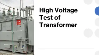
36 36 KV Live Tank CT A transformer is a device which consists of two windings called primary and secondary. A CT for operations on a 110 110 kV grid
It transfers energy from one side to another with suitable change in the level of current Current Transformer or voltage. A current transformer basically has a primary coil of one or more turns of heavy cross-sectional area. In some, the bar carrying high current may act as a primary.
This is connected in series with the line carrying high current. Current Transformer The secondary of the transformer is made up of a large number of turns of fine wire having small cross-sectional area.
Current Transformer This is usually rated for 5 A. This is connected to the coil of normal range ammeter. Symbolic representation of a current transformer is as shown in the figure.
Current Transformer These transformers are basically step up transformers i.e. stepping up a voltage from primary to secondary. Thus the current reduces from primary to secondary.
So from current point of view, these are Current Transformer step down transformer, stepping down the current value considerably from primary to secondary.
Let N1 = Number of turns of primary N2 = Number of turns of secondary I1 = Primary current, I2 = Secondary current Current Transformer V N For a transformer, = 1 1 V N 2 2
2. Potential Transformer The basic principal of these transformers is same as current transformers. The high alternating voltage is reduced in a fixed proportion for the measurement purpose with the help of potential transformers. Potential Transformer
The construction of these transformer is similar to the normal transformer. Potential Transformer These are extremely accurate ratio step down transformers. The windings are low power rating windings.
Primary winding consists of large number of turns while secondary has less number of Potential Transformer turns and usually rated for 110 V, irrespective of the primary voltage rating. The primary is connected across the high voltage line while secondary is connected to the low range voltmeter coil.
Potential Transformer One end of the secondary is always grounded for safety purpose. The connections are shown in the figure.
As a normal transformer, its ratio can be specified as, Potential Transformer V= N 1 1 V N 2 2 So if voltage ratio of P.T. is known and the voltmeter rating is known then the high voltage to be measured, can be determined.
Potential & Current Transformer Application of C.T. and P.T. The C.T.s and P.T.s are used for, 1. Circulating current differential protection. 2. Over current phase fault protection. 3. Distance protection. 4. Intermediate CTs for feeding protective devices, measuring systems, relays etc.
3. Pulse Transformer The pulse transformer is basically a transformer which couples a source of pulses of electrical energy to the load with its shape and other properties maintained. Pulse Transformer Pulse Transformer Pulse Transformer
Working principle of pulse transformer The traditional transformers deals with sinusoidal waveforms, but pulse transformers deals with square pulse waveforms. Signal processing is the vital part of this transformers. Initially, input signal waves are provided in the primary side of pulse transformer, it may be distorted sinusoidal or square pulse signal. But, this distorted signal usually randomize the flux distribution in primary coil. Pulse Transformer
Then the high reluctance path(core) is Pulse Transformer confine those fluxes into it and reduces the leakage fluxes. The distortion of pulses are are also reduced as the core is made by high permeability material.
Then the flux linkages in secondary winding Pulse Transformer leads to develop another pulse series, which is nothing but the dV / dt of the input signal. Amplitude of the pulses are depended upon the turns ratio. So, it gives a distortionless and modified pulse series as the output.
Construction of Pulse Transformer The general construction of pulse transformer are quite similar to that of the power transformers. Pulse Transformer But some special improvement or modification is provided. As they are used in sophisticated electronics applications, therefore the design of that transformers should carried out in such a way, that they can minimize the effects of signal distortion.
The pulse transformers are designed on shell type core construction. The main reason is, shell type core construction provides reduce susceptibility for eddy current as well it can withstand with high voltage level ( specially in case of power pulse transformer ). As those transformers are based on shell type core construction, therefore the capacitance effect in between the primary and secondary winding is reduced. Pulse Transformer
Types of Pulse Transformers In general, pulse transformers are classified Pulse Transformer in two categories, namely signal type pulse transformer and power type pulse transformer. The product of those is termed as voltage time integral. Large voltage time integral means the pulse peak voltages are high.
The classification of pulse transformers Pulse Transformer are done with the help of a determining factor Voltage Time Integral . Each pulse has its peak voltage ( that is the maximum amplitude ) and a certain time period (duration of the pulse).
Pulse Transformer Pulse
Application of pulse transformers Pulse Transformer Small sized pulse transformers, that is signal transformers are used in low voltage electronics applications like camera flasher, and they are also used in controlling of digital logic circuits.
These generated pulse from this type of Pulse Transformer transformers are used for gate turn on process. They are also used in telecommunication system. High voltage pulse transformers, that is power pulse transformers are used in radars, particle acceleration purposes.
4. AudioFrequency Transformer The transformers used in power systems operating at a frequency of 50 Hz transformers power from one voltage level into other. These transformers come across wide range of frequencies i.e. bandwidth of the signal dependent on type of application like audio, video etc.
There are basically two main applications of these transformers used in electronic circuit and handling variable frequencies. Firstly the load is coupled to the source in such a way as to have maximum power to transfer from source to load which requires impedance matching.
Under this case, the efficiency may be as low as 50% but it is not the important consideration Audio Frequency Transformer here. Since the prime importance here is for maximum power transfer rather than maximum efficiency in case of power transformer. These transformers are called output transformers.
If these transformers are employed in audio applications, they are called audio transformers. Secondly these transformers provide a path for dc bias current through its primary circuit while it keeps this current away from secondary circuit. The main factor to be considered in case of these transformers is that the amplitude of voltage gain which is ratio of output voltage to input voltage should remain nearly constant over the range of frequencies. Audio Frequency Transformer
Audio Frequency Transformer The phase shift between input and output voltage should also be small over the working range of frequencies. To study the gain and phase characteristics with frequency , logarithmic scale should be used as frequency range is large.
Audio Frequency Transformer The phase shift between input and output voltage To study these characteristic under various range of frequencies, let us consider the equivalent circuit of the transformer as shown in Fig.
The source is having internal resistance Rs and Audio Frequency Transformer it is driving the load resistance RL . Lo is magnetizing branch inductance inductance while L1 and L2 are leakage inductance of primary and secondary coil respectively. Let us consider the mid frequency region first.
In this region the leakage inductances on both sides be neglected as they cause very small voltage drops while the magnetizing inductance branch treated as open circuit. The equivalent circuit in this is shown in the Fig. Audio Frequency Transformer
' 2 R = Equivalent resistance of secondary referred to primary N Audio Frequency Transformer K 2 = Transformation ratio = N 1
V' L >Now to find out the ratio we can V S use potential divider rule, >We have, R S L S V V + ; Audio Frequency Transformer ' L R = ' ' L ' + + R R R 2 1
= + + ' R R R R > Let 1 2 eq S ' R = ' V V L L S + ' R R eq L Audio Frequency Transformer V V N But = = = ' V . 2 V L L L L K N N 1 2 N 1
Audio Frequency Transformer ' N R = 2. V V L L S + ' N R R 1 eq L Voltage gain, ' V N R = = 2 L L A 0 + ' V N R R 1 S eq L
5.Grounding Transformer Grounding Transformer The grounding transformer is also called earthing transformer. Its main purpose is to provide neutral point for grounding purposes.
When the transformers or generators are delta Grounding Transformer connected or if the neutral points are not accessible then artificially the neutral earthing point can be created with the help of star connected grounding transformer. Such transformer has no secondary winding. Each phase of primary has two equal parts.
There are three Grounding Transformer limbs and each limb has two winding opposite flux during normal condition. Such a transformer is shown in Figure.
One set of winding are connected in star providing the neutral point. The other ends of this set of windings are connected to the second set of windings as shown in the figure. The directions of the currents in the two windings each limb are opposite to each other. Grounding Transformer
This is necessary in systems with operating voltage between 2.2 kV and 3.3 kV These transformer are of short time rating in the rang of 10 seconds to 1 minute. Hence the size of these transformers is small as compared to power transformers of same rating. Grounding Transformer
Reference : U.A.Bakashi, Technical publications Tech-max publications B.L.Thereja www.google.com Wikipedia


 is")