Speed Control of DC Motor Using Chopper Converter and PI Controller
"Learn about the speed control of separately excited DC motors utilizing a chopper converter and PI controller for achieving desired speeds. Understand the principles of chopper operation, DC chopper functionality, and the basic idea behind DC motor speed control. Explore current and speed controller design in detail."

Download Presentation

Please find below an Image/Link to download the presentation.
The content on the website is provided AS IS for your information and personal use only. It may not be sold, licensed, or shared on other websites without obtaining consent from the author. If you encounter any issues during the download, it is possible that the publisher has removed the file from their server.
You are allowed to download the files provided on this website for personal or commercial use, subject to the condition that they are used lawfully. All files are the property of their respective owners.
The content on the website is provided AS IS for your information and personal use only. It may not be sold, licensed, or shared on other websites without obtaining consent from the author.
E N D
Presentation Transcript
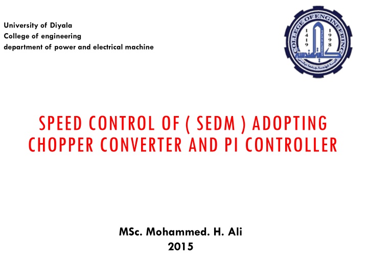
University of Diyala College of engineering department of power and electrical machine SPEED CONTROL OF ( SEDM ) ADOPTING CHOPPER CONVERTER AND PI CONTROLLER MSc. Mohammed. H. Ali 2015
ABSTRACT The speed of separately excited DC motor can be controlled from below and up to rated speed using chopper as a converter. The chopper firing circuit receives signal from controller and then chopper gives variable voltage to the armature of the motor for achieving desired speed. There are two control loops, one for controlling current and another for speed. The controller used is Proportional-Integral type which removes the delay and provides fast control
DC CHOPPER A chopper is a static power electronic device that converts fixed dc input voltage to a variable dc output voltage PRINCIPLE OF CHOPPER OPERATION: A chopper is a high speed on or off semiconductor switch. It connects source to load and disconnect the load from source at a fast speed. In this manner, a chopped load voltage as shown in Fig(1).
V0 = (TON / (TON+TOFF)) * VS Fig(1).
SEPARATELY EXCITED DC MOTOR BASIC OF SEPARATELY EXCITED DC MOTOR Separately Excited DC motor has field and armature winding with separate supply. The field windings of the dc motor are used to excite the field flux. Separately Excited DC motor equivalent circuit Current in armature circuit is supplied to the rotor Via brush and commutator segment for the mechanical work. The rotor torque is produced by interaction of field flux and armature current
BASIC IDEA The basic principle behind DC motor speed control is that the output speed of DC motor can be varied by controlling armature voltage for speed below and up to rated speed keeping field voltage constant. The output speed is compared with the reference speed and error signal is fed to speed controller. Closed loop system model for speed control of dc motor
CURRENT CONTROLLER DESIGN: Block Model for Current controller design
SPEED CONTROLLER DESIGN Block model for Speed Controller design
COMPLETE LAYOUT FOR DC MOTOR SPEED CONTROL Complete layout for DC motor speed control
PROBLEM STATEMENT: A separately excited DC motor with nameplate ratings of 300KW, 420V (DC), 50 rad/sec is used in all simulations. Following parameter values are associated with it. Moment of Inertia J = 75 Kg-m2 . Back EMF Constant = 7 Volt-sec/rad. Rated Current = 700 A. Maximum Current Limit = 1000 A. Resistance of Armature Ra = 0.026 ohm. Armature Inductance La = 0.749 mH. Speed Feedback Filter Time Constant T1 = 22 ms. Current Filter Time Constant T2 = 3ms.
Current Controller Parameter: Current PI type controller is given by: Kc {(1+ TcS)/TcS} Here, Tc = Ta and Kc = RaTa/ (2K2KtT2) Ta = La/Ra = 0.749*10-3/0.026 = 28.80 ms. For analog circuit maximum controller output is 10 Volts. Therefore, Kt = 420/10 = 42. Also, K2 = 10/1000 = 1/100. Now, putting value of Ra, Ta, K2, Kt and T2 we get: Kc = 0.297. Speed Controller Parameter: Speed PI type controller is given by: Kn{(1+TnS)/TnS} Here, Tn = 4 = 4(T1+2T2) = 4(22 + 2*3) = 112 ms. Also, Kn = TmKmK2/(2K1Ra ). K1 = 10/50 = 0.192. Tm = JRa/Km = 75*0.026/7 = 0.278 ms. Now, Kn = (0.278*7*0.01)/ (2*0.192*0.026*31*100) = 6.28.
THE SIMULATION RESULTS AND DISCUSSION From simulation results, it is clear that the SIMULINK model as shown in figure (7) gives larger overshoot in speed before settling to steady state When the load is constant the speed response is smooth after attaining steady state. When load is constant and reference speed is varying (figure 8) then speed response is shifting accordingly with a time delay. But when the load is varying , (figure 9) speed response have ripples due to time delay in achieving desired speed. When Reference speed and load is varying (figure 10) then in speed response, there is some ripple due to delay in achieving current reference speed
Figure (8)Speed Response at reference speed at half rated and full Load speed figure (9)Speed Response at reference speed ,rated speed and half of full Load
figure (10) Speed Response at reference speed of half the rated speed and half of full Load


) * VS")


Speed Response at reference speed")
 Speed Response at reference speed")