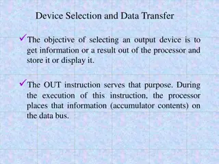
SPI Protocol and DAC Interfacing
In this detailed chapter, you will delve into the intricate workings of the SPI protocol and DAC interfacing, exploring topics such as SPI bus connections, clock polarity and phase modes, SAMD2x SPI module base addresses, registers, and control. Dive deeper into the world of SPI communication and learn about master-slave configurations, serial vs. parallel connections, and more.

Download Presentation

Please find below an Image/Link to download the presentation.
The content on the website is provided AS IS for your information and personal use only. It may not be sold, licensed, or shared on other websites without obtaining consent from the author.If you encounter any issues during the download, it is possible that the publisher has removed the file from their server.
You are allowed to download the files provided on this website for personal or commercial use, subject to the condition that they are used lawfully. All files are the property of their respective owners.
The content on the website is provided AS IS for your information and personal use only. It may not be sold, licensed, or shared on other websites without obtaining consent from the author.
E N D
Presentation Transcript
Chapter 8 SPI Protocol and DAC Interfacing 1
SPI Bus vs. Traditional Parallel Bus Connection to Microcontroller 2
SPI Clock Polarity and phase Mode 0 (CPOL = 0, CPHA = 0) and Mode 2 (CPOL = 1, CPHA = 0) 6
SPI Clock Polarity and phase Mode 1 (CPOL = 0, CPHA = 1) and Mode 3 (CPOL = 1, CPHA = 1) 7
SPI Clock Polarity and phase Clock Polarity 0 0 1 1 Clock Phase 0 1 0 1 Data read and change time SPI Mode read on rising edge, changed on a falling edge read on falling edge, changed on a rising edge read on falling edge, changed on a rising edge read on rising edge, changed on a falling edge 0 1 2 3 8
SAMD2x SPI Module Base Addresses SERCOM Module SERCOM0 SERCOM1 SERCOM2 SERCOM3 SERCOM4 SERCOM5 Base Address 0x42000800 0x42000C00 0x42001000 0x42001400 0x42001800 0x42001C00 9
SAMD2x SPI Registers Register Name Register Function Control A Control B Baud rate Interrupt Enable Clear Interrupt Enable Set Interrupt Flag Status Synchronization Busy Address Receive and Transmit buffer Debug Control Register Address Offset (Hex) 0x00 0x04 0x0C 0x14 0x16 0x18 0x1A 0x1D 0x24 0x28 0x30 CTRLA CTRLB BAUD INTENCLR INTENSET INTFLAG STATUS SYNCBUSY ADDR DATA DBGCTRL 10
CTRLA (Control A) Register Bits Name Function Description 0: MSB is transferred first. 1: LSB is transferred first. 30 DORD Data Order 0: SCK is low when idle. The leading edge of a clock cycle is a rising edge, while the trailing edge is a falling edge. 1: SCK is high when idle. The leading edge of a clock cycle is a falling edge, while the trailing edge is a rising edge. 29 CPOL Clock Polarity 0: The data is sampled on a leading SCK edge and changed on a trailing SCK edge. 1: The data is sampled on a trailing SCK edge and changed on a leading SCK edge. 28 CPHA Clock Phase 27-24 FORM[3:0] Frame Format In master operation, DO is MOSI. In slave operation, DO is MISO. 21-20 DIPO[1:0] Data In Pinout Immediate Buffer Overflow Notification Run In Standby 0: STATUS.BUFOVF is asserted when it occurs in the data stream. 1: STATUS.BUFOVF is asserted immediately upon buffer overflow. This bit defines the functionality in standby sleep mode. 0x2: SPI slave operation 0x3: SPI master operation For UART and I2C options, see relevant chapters 0: The peripheral is disabled or being disabled. 1: The peripheral is enabled or being enabled. 0: There is no reset operation ongoing. 1: The reset operation is ongoing. 8 IBON 7 RUNSTDBY 4-2 MODE Operating Mode 1 ENABLE Enable 0 SWRST Software Reset 12
Interrupt Flag Register Bits Bits Name Function Description 0 DRE Data Register Empty The bit is 1 when the transmit DATA is empty and can accept another byte of data. The bit is 1 when both transmit DATA is empty and the shift register is empty. It is cleared by writing a 1 to it. 1 TXC Transmit Complete 2 RXC Receive Complete The bit is 1 when there is new data in the receive buffer registers. It is cleared when data are read. 18
PMUX register for choosing peripheral functions 20
PORT pin Function multiplexing A (0) EIC B (1) C (2) SERCOM D (3) E (4) TC/TCC TCC2/WO[0] TCC2/WO[1] F (5) TCC G (6) COM H (7) AC/GCLK I/O Pin PA00 PA01 PA02 Supply VDDANA VDDANA VDDANA REF ADC AC PTC DAC SERCOM-ALT SERCOM1/PAD[0] SERCOM1/PAD[1] EXTINT[0] EXTINT[1] EXTINT[2] AIN[0] Y[0] VOUT ADC/VREFA DAC/VREFA ADC/VREFB PA03 VDDANA EXTINT[3] AIN[1] Y[1] PA04 PA05 PA06 PA07 PA08 PA09 PA10 PA11 PA12 PA13 PA14 PA15 PA16 PA17 PA18 PA19 PA20 PA21 PA22 PA23 PA24 PA25 PA27 PA28 PA30 PA31 PB00 PB01 PB02 PB03 PB04 PB05 PB06 PB07 PB08 PB09 PB10 PB11 PB12 PB13 PB14 PB15 PB16 PB17 PB22 PB23 PB30 VDDANA VDDANA VDDANA VDDANA VDDIO VDDIO VDDIO VDDIO VDDIO VDDIO VDDIO VDDIO VDDIO VDDIO VDDIO VDDIO VDDIO VDDIO VDDIO VDDIO VDDIO VDDIO VDDIO VDDIO VDDIO VDDIO VDDANA VDDANA VDDANA VDDANA VDDANA VDDANA VDDANA VDDANA VDDANA VDDANA VDDIO VDDIO VDDIO VDDIO VDDIO VDDIO VDDIO VDDIO VDDIO VDDIO VDDIO EXTINT[4] EXTINT[5] EXTINT[6] EXTINT[7] NMI EXTINT[9] EXTINT[10] EXTINT[11] EXTINT[12] EXTINT[13] EXTINT[14] EXTINT[15] EXTINT[0] EXTINT[1] EXTINT[2] EXTINT[3] EXTINT[4] EXTINT[5] EXTINT[6] EXTINT[7] EXTINT[12] EXTINT[13] EXTINT[15] EXTINT[8] EXTINT[10] EXTINT[11] EXTINT[0] EXTINT[1] EXTINT[2] EXTINT[3] EXTINT[4] EXTINT[5] EXTINT[6] EXTINT[7] EXTINT[8] EXTINT[9] EXTINT[10] EXTINT[11] EXTINT[12] EXTINT[13] EXTINT[14] EXTINT[15] EXTINT[0] EXTINT[1] EXTINT[6] EXTINT[7] EXTINT[14] AIN[4] AIN[5] AIN[6] AIN[7] AIN[16] AIN[17] AIN[18] AIN[19] AIN[0] AIN[1] AIN[2] AIN[3] Y[2] Y[3] Y[4] Y[5] X[0] X[1] X[2] X[3] SERCOM0/PAD[0] SERCOM0/PAD[1] SERCOM0/PAD[2] SERCOM0/PAD[3] SERCOM2/PAD[0] SERCOM2/PAD[1] SERCOM2/PAD[2] SERCOM2/PAD[3] SERCOM4/PAD[0] SERCOM4/PAD[1] SERCOM4/PAD[2] SERCOM4/PAD[3] SERCOM3/PAD[0] SERCOM3/PAD[1] SERCOM3/PAD[2] SERCOM3/PAD[3] SERCOM3/PAD[2] SERCOM3/PAD[3] SERCOM5/PAD[0] SERCOM5/PAD[1] SERCOM5/PAD[2] SERCOM5/PAD[3] TCC0/WO[0] TCC0/WO[1] TCC1/WO[0] TCC1/WO[1] TCC0/WO[0] TCC0/WO[1] TCC1/WO[0] TCC1/WO[1] TCC2/WO[0] TCC2/WO[1] TC3/WO[0] TC3/WO[1] TCC2/WO[0] TCC2/WO[1] TC3/WO[0] TC3/WO[1] TC7/WO[0] TC7/WO[1] TC4/WO[0] TC4/WO[1] TC5/WO[0] TC5/WO[1] I2S/SD[0] I2S/SD[1] I2S/MCK[0] I2S/SCK[0] I2S/FS[0] SERCOM0/PAD[0] SERCOM0/PAD[1] SERCOM0/PAD[2] SERCOM0/PAD[3] SERCOM2/PAD[0] SERCOM2/PAD[1] SERCOM2/PAD[2] SERCOM2/PAD[3] SERCOM1/PAD[0] SERCOM1/PAD[1] SERCOM1/PAD[2] SERCOM1/PAD[3] SERCOM5/PAD[2] SERCOM5/PAD[3] SERCOM3/PAD[0] SERCOM3/PAD[1] SERCOM3/PAD[2] SERCOM3/PAD[3] TCC1/WO[2] TCC1/WO[3] TCC0/WO[2] TCC0/WO[3] TCC0/WO[6] TCC0/WO[7] TCC0/WO[4] TCC0/WO[5] TCC0/WO[6] TCC0/WO[7] TCC0/WO[2] TCC0/WO[3] TCC0/WO[6] TCC0/WO[7] TCC0/WO[4] TCC0/WO[5] TCC1/WO[2] TCC1/WO[3] GCLK_IO[4] GCLK_IO[5] AC/CMP[0] AC/CMP[1] GCLK_IO[0] GCLK_IO[1] GCLK_IO[2] GCLK_IO[3] AC/CMP[0] AC/CMP[1] GCLK_IO[4] GCLK_IO[5] GCLK_IO[6] GCLK_IO[7] X[4] X[5] X[6] X[7] X[8] X[9] X[10] X[11] I2S/SD[0] I2S/SCK[0] I2S/FS[0] USB/SOF 1kHz USB/DM USB/DP GCLK_IO[0] GCLK_IO[0] GCLK_IO[0] SERCOM1/PAD[2] SERCOM1/PAD[3] SERCOM5/PAD[2] SERCOM5/PAD[3] SERCOM5/PAD[0] SERCOM5/PAD[1] TCC1/WO[0] TCC1/WO[1] TC7/WO[0] TC7/WO[1] TC6/WO[0] TC6/WO[1] SWCLK SWDIO(4) AIN[8] AIN[9] AIN[10] AIN[11] AIN[12] AIN[13] AIN[14] AIN[15] AIN[2] AIN[3] Y[6] Y[7] Y[8] Y[9] Y[10] Y[11] Y[12] Y[13] Y[14] Y[15] SERCOM4/PAD[0] SERCOM4/PAD[1] SERCOM4/PAD[2] SERCOM4/PAD[3] TC4/WO[0] TC4/WO[1] TC5/WO[0] TC5/WO[1] TC4/WO[0] TC4/WO[1] TC5/WO[0] TC5/WO[1] TC6/WO[0] TC6/WO[1] TC7/WO[0] TC7/WO[1] TCC0/WO[0] TCC0/WO[4] TCC0/WO[5] TCC0/WO[6] TCC0/WO[7] I2S/MCK[1] I2S/SCK[1] I2S/FS[1] GCLK_IO[4] GCLK_IO[5] GCLK_IO[6] GCLK_IO[7] GCLK_IO[0] GCLK_IO[1] GCLK_IO[2] GCLK_IO[3] GCLK_IO[0] GCLK_IO[1] X[12] X[13] X[14] X[15] SERCOM4/PAD[0] SERCOM4/PAD[1] SERCOM4/PAD[2] SERCOM4/PAD[3] SERCOM5/PAD[0] SERCOM5/PAD[1] 22 TCC0/WO[4] TCC0/WO[5] I2S/SD[1] I2S/MCK[0] SERCOM5/PAD[2] SERCOM5/PAD[3] SERCOM5/PAD[0] TCC1/WO[2]
LTC1661 DAC Control Functions A3 A2 A1 A0 Interrupt Register DAC Register Power Down Status Comments 0 0 0 0 No Change No Update No Change No operation. power-down status unchanged 0 0 0 1 Load DAC A No Update No Change Load input register A with data. DAC outputs unchanged. power-down Status unchanged 0 0 1 0 Load DAC B No Update No Change Load input register B with data. DAC outputs unchanged. power-down status unchanged 0 0 1 1 0 1 0 0 0 1 0 1 0 1 1 0 0 1 1 1 1 0 0 0 - - - - - - - - - - - - - - - Reserved Reserved Reserved Reserved Reserved No Change Update Outputs Wake Load both DAC Regs with existing contents of input Regs. Outputs update. Part wakes up 1 0 0 1 Load DAC A Update Outputs Wake Load input Reg A. Load DAC Regs with new contents of input Reg A and existing contents of Reg B. Outputs update. 1 0 1 0 Load DAC B Update Outputs Wake Load input Reg B. Load DAC Regs with existing contentsof input Reg A and new contents of Reg B. Outputs update 1 0 1 1 1 1 0 0 1 1 0 1 - - - - - - Reserved Reserved No Change No Update Wake Part wakes up. Input and DAC Regs unchanged. DAC outputs reflect existing contents of DAC Regs 1 1 1 0 No Change No Update Sleep Part goes to sleep. Input and DAC Regs unchanged. DAC outputs set to high impedance state 25 1 1 1 1 Load ADCs A, B with same 10-bit code Update Outputs Wake Load both input Regs. Load both DAC Regs with new contents of input Regs. Outputs update. Part wakes up


 Register in SAMD2x")
 Register")
 Registers in SAMD2x")


 Register")

")