Explore methods to stabilize non-inverting Op-Amp gain for optimal performance, including insights on capacitors, phase margins, and stability testing. Discover practical strategies to enhance stability without the need for significant redesigns, considering factors like parallel capacitors, band-pass filters, and low-pass filters.
Please find below an Image/Link to download the presentation.
The content on the website is provided AS IS for your information and personal use only. It may not be sold, licensed, or shared on other websites without obtaining consent from the author. If you encounter any issues during the download, it is possible that the publisher has removed the file from their server.
You are allowed to download the files provided on this website for personal or commercial use, subject to the condition that they are used lawfully. All files are the property of their respective owners.
The content on the website is provided AS IS for your information and personal use only. It may not be sold, licensed, or shared on other websites without obtaining consent from the author.
E N D
Presentation Transcript
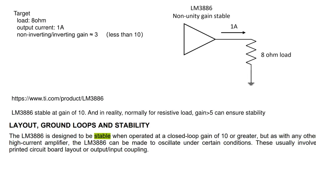
Target load: 8ohm output current: 1A non-inverting/inverting gain 3 less than 10 https://www.ti.com/product/LM3886 LM3886 stable at gain of 10. And in reality, normally for resistive load, gain>5 can ensure stability
Target load: 8ohm output current: 1A Question: Now non-inverting/inverting gain 4, with 1pF~3pF capacitor parallel with Rf, I can probably make it stable Better setting gain 1 or 2. Since the customer has already has the fixed signal generation stageit is quite costly to redesign For LM3886, Better setting gain 1 or 2, parallel capacitor doesn t work too much. May I ask other method (and some related post) for non-unity gain stable (decompensated) op-amp, rather than parallel capacitor? For example, band pass filter? Low pass filter (SK)..
Simulation Non-inverting gain = 1, Phase margin = 23 Reality: Very strong oscillation when I open power supply
Simulation Non-inverting gain = 3, Phase margin = 58 Reality: Sometimes stable, sometimes not.----PCB reason
Simulation Non-inverting gain = 3, with 1pF, Phase margin =64 Non-inverting gain = 3, with 2pF, Phase margin =69 Reality: Sometimes stable, sometimes not.----PCB reason & I use long wire and througn hole 5pF&5pF&5pF for temprary tesing----1pF/2pF/3pF is on the way...
Simulation Non-inverting gain = 4, with 1pF, Phase margin =72 Non-inverting gain = 4, with 2pF, Phase margin =80 Non-inverting gain = 4, with 2pF, Phase margin =86 Reality: stable I use long wire and througn hole 5pF&5pF&5pF for temprary tesing----1pF/2pF/3pF is on the way...