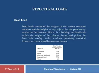
Structural Loads and Forces in Ship Engineering
Ship structures face unique challenges due to their large size and complex shapes, requiring a robust support system to withstand dynamic and random loads in various environments. This article discusses distributed forces, buoyancy, displacement, and shear stress in ship structures, highlighting the importance of structural integrity in maritime engineering.

Uploaded on | 0 Views
Download Presentation

Please find below an Image/Link to download the presentation.
The content on the website is provided AS IS for your information and personal use only. It may not be sold, licensed, or shared on other websites without obtaining consent from the author. If you encounter any issues during the download, it is possible that the publisher has removed the file from their server.
You are allowed to download the files provided on this website for personal or commercial use, subject to the condition that they are used lawfully. All files are the property of their respective owners.
The content on the website is provided AS IS for your information and personal use only. It may not be sold, licensed, or shared on other websites without obtaining consent from the author.
E N D
Presentation Transcript
Ship Structural Loads Sections 6.1 6.2
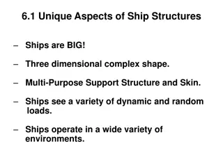
Unique Aspects of Ship Structures Ships are BIG! Three dimensional complex shape. Multi-Purpose Support Structure and Skin. Ships see a variety of dynamic and random loads. Ships operate in a wide variety of environments.
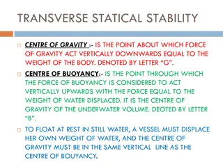
Ship Structural Loads Distributed Forces displacement ( ) & buoyancy (??) Resultant displacement force due to the distributed weight of the ship G B WL Result force buoyancy due to the distributed buoyancy ?? For a floating body in static equilibrium Two forces are equal in magnitude. The centroid of the forces are vertically in line.
Distributed Force Bouyancy Distributed Buoyancy Buoyant forces can be considered as a distributed force. 50 ft Barge Uniformly Distributed Buoyant Force (??) 2 LT/ft 2 ?? ?? ??= 50 ?? = 100 ??
Distributed Displacement Displacement of a ship can also be presented as a distributed force. Case I : Uniformly Distributed Weight 2 LT/ft 50 ft Barge 2 ?? ?? 2 LT/ft = 50 ?? = 100 ?? = ??
Distributed Displacement Case II : Non-Uniformly Distributed Weight 10ft 4 LT/ft 2 LT/ft 2 LT/ft 1 LT/ft 1 LT/ft Barge 50 ft 2 LT/ft 1 ?? ?? 10 ?? +2 ?? 10 ?? +4 ?? 10 ?? +2 ?? 10 ?? +1 ?? = 10 ?? = 100 ?? = ?? ?? ?? ?? ?= ?? ?? 100 ?? 50 ??=2 ?? ??????= ??
Shear Stress 4 LT/ft Shear stress present at points O, P, Q, R, S & T due to unbalanced forces at top and bottom. Load diagram can be drawn by summing up the distributed force vertically. 2 LT/ft 2 LT/ft 1 LT/ft 1 LT/ft O P R S T Q 2 LT/ft O P Q R S T Load Diagram 0 LT/ft = 2 LT/ ft 2 LT/ft 0 LT/ft = 2 LT/ ft 2 LT/ft - 2 LT/ft = 2 LT/ft - 4 LT/ft 1LT/ft = 2 LT/ ft 1 LT/ft 1LT/ft = 2 LT/ ft 1 LT/ft Shear Force at points
Shear Stress Maximum shear stresses occurs at points Q and R where a zero crossing occurs and the magnitudes have the largest change. P Q O S R T Load Diagram -2LT/ft 1LT/ft 1LT/ft
Shear Stress How to Reduce Shear Stress of Ship Change the underwater hull shape so that buoyancy distribution matches that of weight distribution. The step like shape is very inefficient with regard to the resistance Since the loading condition changes frequently, this method is not feasible. Design to concentrate the ship hull strength in an area where large shear stress exists. Using higher strength material Increasing the cross sectional area of the structure.
Longitudinal Bending Moment Longitudinal Bending Moment Uneven load distribution will produce: Longitudinal Bending Moment Bending Moment Buoyant force concentrates at bow and stern. Displacement concentrates at middle of ship. The longitudinal bending moment will create a significant stress in the structure called bending stress.
Longitudinal Bending Moment Sagging Weather Deck : Compression Bending Moment Smile Keel : Tension Bow Stern Hogging Weather Deck : Tension Hill Bow Stern Bending Moment Keel : Compression
Longitudinal Bending Moment Sagging & Hogging on Waves The worst bending moments occur when the length of the ship is nearly equal to the length of the waves. Sagging Condition Crest Crest Trough Buoyant force is greater at wave crests. Hogging Condition Crest Trough Trough
Longitudinal Bending Stress The longitudinal bending moment creates a significant structural stress called the Bending Stress (???????? ) ? ? ? ???????? = On Equation Sheet (Chapter 5 & 6) Where: M = Bending Moment I = 2nd Moment of area of the cross section y = Vertical distance from the neutral axis ???????? = tensile (+) or compressive(-) stress
Quantifying Bending Stress Sagging Condition A Compression y A ???????? B B Tension Neutral Axis ? ? ? Neutral Axis: Geometric centroid of the cross section or transition between compression and tension. Bending stress is 0 on the neutral axis. ???????? = ???????? = tensile (+) or compressive (-) stress
Quantifying Bending Stress Hogging Condition y Tension A A B B Compression ? ? ? Neutral Axis ???????? = ???????? = tensile (+) or compressive (-) stress
Bending Stress of Ship Hull Deck Bow Stern A Neutral Axis B Keel Cross Section A Deck : Compression Keel : Tension B Ship could be at sagging condition even in calm water Generally, bending moments are largest at the midship area.
Bending Stress of Ship Hull Neutral Axis Shift Bow Stern Deck A Neutral Axis B Cross Section Keel y A Deck Neutral Axis This ship has lager magnitude of bending stress at keel than deck due to the position of the neutral axis. B Keel
Reducing the Effect of Bending Stress Bending moment are largest at amidships of a ship. Ship will experience the greatest bending stress at the deck and keel. The bending stress can be reduced by using: Higher strength steel Larger cross sectional area of longitudinal structural elements
Hull Structure Interaction Bending stress at the superstructure is large because of its distance from the neutral axis. Sagging or Hogging condition, severe shear stresses between deck of hull and bottom of the superstructure will be created This shear stresses will cause crack in area of sharp corners where the hull and superstructure connect. This stress can be reduced by an Expansion Joint By using Expansion Joint, the super structure will be allowed to flex along with the hull.
Example Problem A 100ft long box shaped barge has an empty weight distribution of 2LT/ft. What is the total buoyant force floating the empty barge in calm water? The barge is then loaded with the additional cargo weight distribution shown below. What is the buoyant force distribution in calm water for the loaded barge? Draw the load diagram. At which point, (A, B, C or D) is the barge under the greatest shear stress? Is the barge in a hogging or sagging condition? If a wave hits which peaks at the center of the barge and troughs at the ends, is the condition above mitigated or exacerbated? 4LT/ft 3LT/ft 2LT/ft 20ft 20ft 20ft 30ft 10ft C A B D 100ft