Studies on Action Potentials and Membrane Models
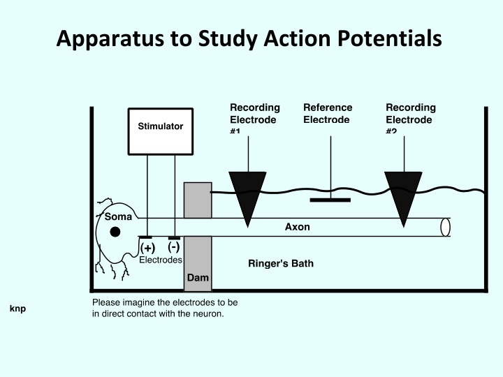
These images showcase various apparatus, stimuli, responses, and components related to action potentials and membrane models in biological systems. The importance of low capacity DC generators and the structural implications of membrane models are explored, along with the events of an action potential and the use of voltage clamps to study membrane currents. The historical context and structural validity of different membrane models are also discussed.
Download Presentation

Please find below an Image/Link to download the presentation.
The content on the website is provided AS IS for your information and personal use only. It may not be sold, licensed, or shared on other websites without obtaining consent from the author.If you encounter any issues during the download, it is possible that the publisher has removed the file from their server.
You are allowed to download the files provided on this website for personal or commercial use, subject to the condition that they are used lawfully. All files are the property of their respective owners.
The content on the website is provided AS IS for your information and personal use only. It may not be sold, licensed, or shared on other websites without obtaining consent from the author.
E N D
Presentation Transcript
Membrane Model The dc generator is very low capacity. What does this means (structurally)?
Membrane Model #2 This model is valid ONLY for a very thin section of the length of an axon (or muscle fiber). This sort of model was hypothesized by the late 1940s
The Voltage Clamp, part 1 In order for Em to change, the total charge (Q) across the membrane capacitance (Cm) must change. For Q to change, a current must flow. (Obviously!) However, any current associated with the membrane has two components: one associated with charging or discharging the Cm(called iC) another,iR, associated with current flow through the various parallel membrane resistances, lumped together asRM. Thus: iM = iC + iR
The Voltage Clamp, part 2 We can only measure TOTAL membrane current, im directly. But, we are most interested in the "resistive" current components because these are associated with ionic movements through channels and gates. -- Is there a way to separate ir from the capacitive current, iC?
The Voltage Clamp, part 3 QC= EC*CM =VC*CM Recall that: If we take the time derivative of the last equation (to get current flowing in or out of the capacitance, ic): dQc dt dVc dt = CM dVc dt iC= CM
The Voltage Clamp, part 4 If we substitute the expression for iC (last slide) into the total membrane current equation, we get: im= iR+dV dTCM im= iR+iC Reminder: total membrane current, im, is: If there is some way to keep the transmembrane potential (Em) constant (dV/dt=0) then: im= iR Thus, if EM is constant, then any current we measures is moving through the membrane resistance(s) i.e., these currents are due to specific ions moving through specific types of channels.
How can we keep Em constant during a time (the AP) when Em normally changes rapidly? Answer: we use a device called the voltage clamp to deliver a current to the inside of the cell -- initially to change Em to some new clamped voltage and then in such a way as to prevent Em from changing i.e., in a way to hold Em constant. The clamp senses minute changes in (dEm) due to ions moving through membrane channels (rm) and into or out of the membrane capacitor, Cm. The clamp applies charge to the electrodes (a current) to stop this movement and keep Em essentially constant. Thus, capacitive current is zero as is the resistive current. Whatever current was applied by the clamp was equal and opposite to whatever im tried to flow.
Review of Membrane Model Let s review what we think we know about current flows in a resting cell.
Voltage Clamp Data for a Stimulus that Would Elicit an AP in a Non-Clamped Cell Both of these clamp Em values are well above threshold and would normally elicit an AP.
Inward and Outward Currents at Two Clamp Potentials
Using Clamp Data to Find Membrane Conductances Ohm s Law: iion = Eion * R-1ion The emf for a particular ion (Eion) is the difference between Em and the ion's Nernst potential. Thus: iion = Gion * (Em - Eion)
Calculation of the Conductance Changes During an AP We must calculate the conductances (G) for each ion with respect to time. To do this, you simply use the conductance equation with the clamp voltage as Em, the ion s Donnan equilibrium voltage and the current (calculated from voltage clamp data) at any moment of time Thus: Gion at time t = (iion at time t )/ (Em - Eion)
Conductances During An AP
Finding Em with the Goldman-Hodgkin-Katz Equation (a.k.a. Goldman or Goldman Field eq.) EM= -58*logGcation1*[cation1]in+Gcation2*[cation2]in+Ganion1*[anion1]out Gcation1*[cation1]out+Gcation2*[cation2]out+Ganion1*[anion1]in
Our Latest Membrane Model Could this be further modified?
Populations of Channels and Voltage- Gated Channels How do we modify our model to take into account several types of K+ channels?
