System Integration and Data Modeling in Healthcare
Explore the existing system structure and the vision for a new integrated system in healthcare, including data models, service tables, medication data, diagnosis states, and lab service states. Learn about the context diagram and supplier integration with external systems for efficient patient management.

Download Presentation

Please find below an Image/Link to download the presentation.
The content on the website is provided AS IS for your information and personal use only. It may not be sold, licensed, or shared on other websites without obtaining consent from the author. If you encounter any issues during the download, it is possible that the publisher has removed the file from their server.
You are allowed to download the files provided on this website for personal or commercial use, subject to the condition that they are used lawfully. All files are the property of their respective owners.
The content on the website is provided AS IS for your information and personal use only. It may not be sold, licensed, or shared on other websites without obtaining consent from the author.
E N D
Presentation Transcript
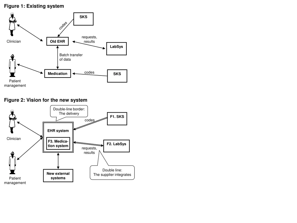
Figure 1: Existing system SKS requests, results Clinician Old EHR LabSys Batch transfer of data codes Medication SKS Patient management Figure 2: Vision for the new system Double-line border: The delivery F1. SKS codes EHR system Clinician F3. Medica- tion system F2. LabSys requests, results Double line: The supplier integrates New external systems Patient management
Figure 3. Data model for the system Person ID, Name . . . D5. Person Plus 12 more boxes State, Start, End, Name D6. Admission Name, Start time, State (obs | valid | canceled | closed), . . . recommendation Consists of D1. Diagnosis D3. Service Start time, State ( . . .), . . . Dotted box: Shared with external system Diagnosis code, Name, State (considered | . . .), Description, Recommendation Hierarchy D2. Diagnosis Type D4. Service Type Service code, Name, State (. . .), . . . Hierarchy
Figure 5. Present medication data Start End Type Medicine Unit Dosis Daily dosis Path Info Solid.Inf. Solid Solid.Inf. Solid Solid Solid Solid Solid Solid
Figure 6. Diagnosis states Clinician Canceled Obs any state Automatic (20 years) Valid Closed Clinician
Figure 7. LabSys service states and messages LabConfirm Clinician Clinician Started Ordered Confirmed Clinician LabSample LabRequest LabSys Completed changed LabRequest Doctor any state Canceled any state Assessed LabCancel Clinician Automatic (20 years)
Figure 8. Context diagram F1. SKS codes EHR system Clinician F3. Medica- tion system F2. LabSys requests, results Double line: The supplier integrates F10. New external systems Patient management