System-Level Simulation Considerations for HEW Technologies
Explore system-level simulation scenarios for evaluating HEW technologies in different environments, focusing on outdoor large BSS hotspot scenarios and preliminary evaluation results. Parameters, methodology, and key considerations are discussed to provide insights into the performance and optimization of wireless networks.

Download Presentation

Please find below an Image/Link to download the presentation.
The content on the website is provided AS IS for your information and personal use only. It may not be sold, licensed, or shared on other websites without obtaining consent from the author. If you encounter any issues during the download, it is possible that the publisher has removed the file from their server.
You are allowed to download the files provided on this website for personal or commercial use, subject to the condition that they are used lawfully. All files are the property of their respective owners.
The content on the website is provided AS IS for your information and personal use only. It may not be sold, licensed, or shared on other websites without obtaining consent from the author.
E N D
Presentation Transcript
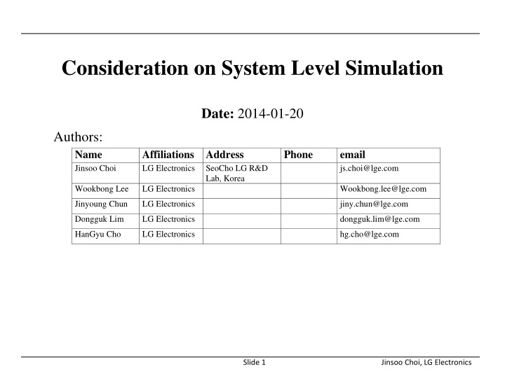
Consideration on System Level Simulation Date: 2014-01-20 Authors: Name Jinsoo Choi Affiliations Address LG Electronics Phone email js.choi@lge.com SeoCho LG R&D Lab, Korea Wookbong Lee LG Electronics Wookbong.lee@lge.com Jinyoung Chun LG Electronics jiny.chun@lge.com Dongguk Lim LG Electronics dongguk.lim@lge.com HanGyu Cho LG Electronics hg.cho@lge.com Slide 1 Jinsoo Choi, LG Electronics
Introduction In simulation scenarios document [1], we defined five simulation scenarios to enable verification of the proposed HEW technologies performance in different environment In outdoor large BSS hotspot scenario, followings are expected - Channel variation and longer inter-cite distance (ICD) than other scenarios Possibility of degraded system throughput from selecting low MCSs - Relatively higher AP transmit power than other scenarios Possibility of turning off multi-BSSs Tx opportunity In this contribution, we provide preliminary evaluation results based on [1] and some consideration points to evaluate this scenario Slide 2 Jinsoo Choi, LG Electronics
Parameters on simulation scenario Other default parameters: [1] Simulation scenario (Channel model) Scenario-4 (UMi), Indoor user portion: 0% Environment description 19 hexagonal grid with ICD = 130m (Wrap around off) STAs type 2.4GHz, 50 STAs in a BSS BW 20MHz (64 FFT) 1ms TXOP less fixed overhead - Overhead (RTS/CTS off): SIFS + ACK + 2*PLCP header - Overhead (RTS/CTS on): 3*SIFS + RTS + CTS + ACK + 4*PLCP header Data size GI Long (0.8 us) Place APs on the center of each BSS with 0 standard deviation (fixed) AP height: 10m, STA height: 1.5m [2] APs location (AP, STA) = Case-1(30dBm, 15dBm), Case-2(23dBm, 15dBm), Case-3(15dBm, 15dBm) AP & STA TX power Noise figure 7dB for both DL and UL Antennas for AP & STA 2 by 2 with STBC for both links (1-stream) Max # of retries 10 DL & UL traffic Full buffer (DL & UL ratio: based on PHY system simulation in [3]) Slide 3 Jinsoo Choi, LG Electronics
Evaluation methodology: PHY system simulation [3] Simulation assumptions Time aligned TXOPs among BSSs Link adaptation MCS selection based on estimated SNR of the last frame, and modified by ACK statistics [1] No transmission mode selection A subset of MAC features CCA level Preamble detection: -82dBm (both AP and STA) Energy detection: -62dBm (both AP and STA) RTS/CTS on/off (Used for CCA comparison. No actual Tx) Fixed amount of overhead (assuming MCS0 simply) Without RTS/CTS: 29 symbols With RTS/CTS: 69 symbols PHY abstraction: MMIB [4] with extension to 256QAM (MCS8) Slide 4 Jinsoo Choi, LG Electronics
Multi-BSSs idle/busy decision to TX Idle/busy state based on CCA Check interfering signal power from all BSSs to exceed CCA threshold value Any BSS which exceeds the threshold is set to busy state to TX Procedure with RTS/CTS Simulation assumption: Each TXOP contains one data packet (RTS/CTS + Data + ACK) In a TXOP, any BSS which hears interfering signal from neighbor BSSs to exceed CCA threshold value in either DL or UL link is set to busy state to TX Slide 5 Jinsoo Choi, LG Electronics
Performance results RTS/CTS off MCS MCS Tx power (dBm) (AP, STA) DL Tput (Mbps) DL packet loss (%) UL Tput (Mbps) UL packet loss (%) DL:UL Tx ratio (%) Total Tput (Mbps) Total packet loss (%) BSS idle portion (%) * portion (%) (MCS0, MCS8) portion (%) (MCS0, MCS8) Case-1 4.5 1.5 (45, 41) 5.72 3.52 (53, 16) 20:80 10.22 3.02 5.62 Case-2 3.92 2.29 (56, 21) 5.94 1.8 (57, 13) 32:68 9.86 1.97 0.74 Case-3 2.57 3.0 (64, 14) 6.53 0.975 (59, 10) 32:68 9.1 1.6 0.2 *: Average portion that all devices in a BSS is idle Observation Higher UL Tx portion makes higher UL Tput than DL BSS idle portion is very low - System gets high Tx opportunity not critically depending on AP power variation - But, low MCSs (especially MCS0) are used as more than a half of portion (difficult of getting high throughput) => Total system throughput can be limited by the used MCS distribution : Necessity of some clear channel protection Slide 6 Jinsoo Choi, LG Electronics
MCS distribution RTS/CTS off 0.7 0.7 MCS 0 MCS 1 MCS 2 MCS 3 MCS 4 MCS 5 MCS 6 MCS 7 MCS 8 MCS 0 MCS 1 MCS 2 MCS 3 MCS 4 MCS 5 MCS 6 MCS 7 MCS 8 0.6 0.6 0.5 0.5 0.4 0.4 0.3 0.3 0.2 0.2 0.1 0.1 0 0 Case-1 Case-2 Case-3 Case-1 Case-2 Case-3 <Used MCSs in UL> <Used MCSs in DL> MCS0 is a dominant MCS to be used in the simulation - Including very low estimated SINR condition (assuming no minimum MCS requirement) Slide 7 Jinsoo Choi, LG Electronics
Performance results RTS/CTS on MCS MCS Tx power (dBm) (AP, STA) DL Tput (Mbps) DL packet loss (%) UL Tput (Mbps) UL packet loss (%) DL:UL Tx ratio (%) Total Tput (Mbps) Total packet loss (%) BSS idle portion (%) portion (%) (MCS0, MCS8) portion (%) (MCS0, MCS8) Case-1 7.5 0.48 (13, 82) 4.81 1.97 (28, 56) 50:50 12.31 1.17 68.23 Case-2 11.2 1.19 (17, 71) 7.94 2.08 (28, 52) 50:50 19.14 1.61 42.02 Case-3 9.46 1.67 (23, 59) 10.1 1.61 (20, 63) 50:50 19.56 1.64 41.76 Observation Higher MCS portion becomes larger than that without RTS/CTS - Total system Tput is enhanced (about 20 ~ 95%), even in significant BSS idle condition As AP Tx power is getting down, - Both DL and UL Tput increase (some cross point exists in DL case) - High BSS idle situation is getting relaxed Strong AP power could turn off other BSS Tx opportunity : Necessity of AP power alleviation Slide 8 Jinsoo Choi, LG Electronics
MCS distribution RTS/CTS on 1 0.8 MCS 0 MCS 1 MCS 2 MCS 3 MCS 4 MCS 5 MCS 6 MCS 7 MCS 8 MCS 0 MCS 1 MCS 2 MCS 3 MCS 4 MCS 5 MCS 6 MCS 7 MCS 8 0.8 0.6 0.6 0.4 0.4 0.2 0.2 0 0 Case-1 Case-2 Case-3 Case-1 Case-2 Case-3 <Used MCSs in DL> <Used MCSs in UL> MCS8 is a dominant MCS to be used in the simulation - Because of reliable Tx condition by RTS/CTS protection - Possibility of using more increased MCS (FFS) Slide 9 Jinsoo Choi, LG Electronics
Summary Consideration points from our system simulation results on scenario-4 - Point-1: MCS distribution Higher MCSs are used, more increased system throughput is expected In multi-BSS environment, using channel protection like RTS/CTS can make those condition more guaranteed (currently we have RTS/CTS threshold [TBD] in [1]) - Point-2: AP power alleviation High AP power in a BSS can turn-off other BSS s Tx opportunity From the system performance point of view, some AP power calibration may be considerable (e.g. from 30dBm to 23dBm or less) Next steps - Checking on some modification in the simulation scenario document, if needed - More verifying the results and finding out calibration points of other simulation scenarios Slide 10 Jinsoo Choi, LG Electronics
Reference [1] 13/1001r5, Simulation Scenarios Document Template , Simone Merlin (Qualcomm) [2] 13/1383, System Level Simulation Parameters , Wookbong Lee (LG Electronics) [3] 13/1051r1, Evaluation Methodology , Ron Porat (Broadcom) [4] 13/1059, PHY Abstraction for HEW Evaluation Methodology, Dongguk Lim (LG Electronics) Slide 11 Jinsoo Choi, LG Electronics
Appendix: User throughput distribution Slide 12 Jinsoo Choi, LG Electronics