Systems Engineering Processes Module: Understanding System Characteristics
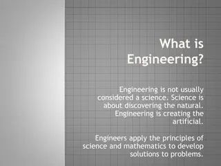
In this module, explore the fundamental aspects of a system such as boundaries, environments, and components. Learn about system hierarchies, purpose, and lifecycle phases. Discover different process models used in systems engineering, including the Waterfall and Spiral models. Gain insights into bringing systems into being, engineering principles, integration, iteration, and implementation techniques.

Download Presentation

Please find below an Image/Link to download the presentation.
The content on the website is provided AS IS for your information and personal use only. It may not be sold, licensed, or shared on other websites without obtaining consent from the author. If you encounter any issues during the download, it is possible that the publisher has removed the file from their server.
You are allowed to download the files provided on this website for personal or commercial use, subject to the condition that they are used lawfully. All files are the property of their respective owners.
The content on the website is provided AS IS for your information and personal use only. It may not be sold, licensed, or shared on other websites without obtaining consent from the author.
E N D
Presentation Transcript
SENG 5130 SYSTEMS ENGINEERING PROCESSES MODULE 14 A SYSTEM
Module 14 Last Lecture
Remember remember Module 1 - Introduction
A system Boundary Environment Interrelationship Component
System Environment Outside of the system boundary Outside system s control Influences (or is influenced by ) system s performance
Characteristics of a system Constitutes a complex combination of resources Is contained within some form of hierarchy May be broken down into subsystems and related components that interact with each other Must have a purpose (defined need, goals and objectives which must be clearly stated by the user)
3 Phase Lifecycle Definition Development Deployment
Remember remember Module 2 Bringing systems into being
Objective for Module 2 Principles and processes To engineer a system Integration and iteration in system design Implementation of systems engineering and analysis
Process Models of Systems Engineering The Waterfall model Spiral Model Generic Vee Model Evolutionary Model Incremental Development Model
The Waterfall Model The waterfall model of the software life cycle. Source: SOFWARE ENGINEERING ECONOMICS by Bohem, B.W.
Vee Process Model Testing Full system operation and verification Define system requirements Allocate system functions to sub-systems Verification of sub- systems Detail design of components Verify components
Evolutionary Process Model A complete, or virtually complete, software system is developed at each of several repetitions of the life cycle Allows for full development of user requirements over time Figure 2.21 (Sage & Armstrong, 2000)
Incremental Development Model (Sage & Armstrong, 2000)
Hybrid Process Model Rapid Prototyping Spiral Need Refined Requirements Evaluate Analysis Requirements Allocation Evaluate Design Validated Requirements Rapid Prototype Incremental Design Build Integrate Minor Modifications Test Modify Deploy
Remember remember Module 3 Conceptual Design Phase
Conceptual Design Domain of customer Functional design Responsibility of the customer What does the system need to do? How well?
Conceptual Design 1. Identification of stakeholder requirements 2. Feasibility analysis 3. Requirements analysis 4. System-level synthesis 5. System design review Preliminary Design
Remember remember Module 4 Preliminary Design
Preliminary Design Responsibility: Contractor (whose responsibility was Conceptual Design?) Customer s role: Monitoring Reviewing Supporting contractor progress
Preliminary Design 1. Subsystem requirements analysis 2. Requirements allocation 3. Interface identification/design 4. Subsystem-level synthesis 5. Preliminary design review
Remember remember Module 5 Detailed Design and Development
The Big Picture Operational Use and System Support Detailed Design and Development Conceptual Design Preliminary Design Production/ Construction System/Program Milestones Disposal/Retirement Updated Product Baseline Functional Baseline Allocated Baseline Product Baseline NEED System Engineering Management Plan Test and Evaluation Master Plan Conceptual Design Review System Design Review Equipment/Software Design Reviews Critical Design Review System Engineering Requirements Modifications for Improvement Modifications for Improvement System Level Sub- System Level Component Level
Detailed Design Realization and documentation of individual components Describe lower-level components Define component characteristics Finalize design of all interfaces Procure items for development Develop and test prototype Conduct critical design review
Detailed Design and Development Processes Revise development specifications Define detailed requirements for units, assemblies, and components Define detailed requirements for interfaces Until satisfactory Produce product specifications Until complete Conduct detailed design of units, assemblies, and components Buy, build, and integrate (prototype) Finalize product, material, and process specifications To Construction and Production
Engineering Design Review Process Interim Product Specification From Conceptual & Preliminary Design Review for Compliance with System Requirements Prepare and submit change recommendation Are No Yes Conduct formal design review requirements satisfied? Yes No Change Approval? Design Approval? No Return to Detailed Design Yes Meeting to evaluate alternatives Product Baseline Yes Agreement?
Remember remember Module 6 System Test, Evaluation and Validation
Objectives of this Module Systems Engineering Management/SEMP Risk Management System Test, Evaluation and Validation 1. 2. 3.
Management and Technology Applied to the Systems Engineering Process Concept design Preliminary system design Detail design and development Production and/or construction System operation and support Retirement and phase-out
SEMP Generic Approach SYSTEM ENGINEERING MANAGEMENT PLAN (SEMP) PART III PART II PART I ENGINEERING SPECIALTY INTEGRATION SYSTEM ENGINEERING PROCESS TECHNICAL PROGRAM PLANNING, IMPLEMENTATION, AND CONTROL Described the system engineering process as it applies to the definition of system requirements and the development of those requirements into a final product configuration. Describes the system requirements in the various engineering specialty areas and the integration of these specialty areas into the overall mainstream engineering design and development effort. Describes the technical program tasks that must be planned and implemented in the fulfillment of system engineering management objectives. Needs analysis Feasibility analysis Operational requirement Maintenance concept Technical performance measures Functional analysis Requirements allocation Synthesis Design integration Design review Test & evaluation Utilization and support Modification/improvement Retirement and disposal Functional engineering Reliability engineering Maintainability engineering Human factors engineering Safety engineering Software engineering Logistics engineering Producibility Affordability Disposability Quality engineering Other engineering disciplines Statement of work Planning products (WBS, Network, Schedule, Costing, Reporting) Supplier requirements Organization al relationships Technical interface management Program management Risk management
Boehms Model Parameters Risk Identification Checklists Decision-driver analysis Decomposition Performance models Cost models Network analysis Decision analysis Quality-factor analysis Risk Analysis Risk Assessment Risk Prioritization Risk exposure Risk leverage Compound-risk reduction Risk Management Buying information Risk avoidance Risk transfer Risk reduction Risk-element planning Risk-plan integration Risk Mgt Planning Prototypes Simulations Benchmarks Analyses Staffing Risk Resolution Risk Control Source: Boehm, B. (1991). "Software Risk Management: Principles and Practices" IEEE Software, 8 (1), 32-41. Risk Monitoring Milestone tracking Top 10 tracking Risk reassessment Corrective action
Stages of system test and evaluation during the life cycle. 5 4 3 2 1
Remember remember Module 7 MidTerms!
Remember remember Module 8 Alternatives and Models in Decision Making
Objectives Decision Analysis Tools Decision Making under Uncertainty Decision Making under Risk Modeling and Simulation 1. 2. 3. 4.
Decision Analysis Tools Decision Trees Decision Matrix (Pay off Matrix) Cost/Benefit Analysis Force Field Analysis Grid Analysis Paired Comparison Analysis Intuition 1. 2. 3. 4. 5. 6. 7.
IMPORTANT: Uncertainty = No Probability Risk = Probability
Decision Making Under Uncertainty Maximax Criterion Extremely Optimistic: Choose decision with the 1. maximum of the maximum payoffs Maximin Criterion Extremely Pessimistic: Choose decision with the maximum of the minimum payoffs 2. Hurwicz Criterion 3. Choose decision in which decision payoffs are weighted by a coefficient of optimism, alpha Coefficient of optimism is a measure of a decision maker s optimism from 0 (completely pessimistic) to 1 (completely optimistic)\ In absence of probabilities, assume equal likelihood Laplace Criterion 4.
3 Modeling Paradigms SD DES ABM Less Detailed More Detailed Macro Continuous Micro Discrete
Remember remember Module 9, 10 Capability Maturity Model Integration (CMMI)
Capability Maturity Model Integration A process improvement framework CMMI- Svc CMMI- Acq CMMI- Dev Core CMMI
Maturity Levels Continuous Representation Capability Levels Staged Representation Maturity Levels Level Level 0 Incomplete Initial Level 1 Performed Managed Level 2 Managed Defined Level 3 Defined Quantitatively Managed Level 4 Optimizing Level 5
Remember remember Module 11 Model Based Systems Engineering Part 1
SE Practices for Describing Systems OMG, 2008
OMG Products Common Object Request Broker Architecture (CORBA) standard Model Driven Architecture Unified Modeling Language (UML) UML + Systems Engineering (INCOSE) = SysML
SysML Graphical modeling language Supports the specification, analysis, design, verification, and validation of systems that include hardware, software, data, personnel, procedures and facilities. SysML IS a visual modeling language that provides semantics (meaning) and notation (representation of meaning) SysML IS NOT a methodology or a tool It is methodology and tool independent Tools: IBM Rational Rhapsody Developer, MagicDraw + SysML plugin, Papyrus for SysML, Modelio Open Project, etc.)
Use Case Diagram Relationships: INCLUDE For this to be COMPLETED This MUST BE DONE <<include>> Use Case A Use Case B Included (the addition) Use Case Including (the base) Use Case