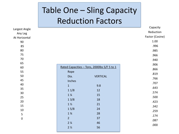
Table One - Sling Capacity Reduction Factors
This information covers sling capacity reduction factors based on cosine values, along with details on poly-yarn PSI max effective contact and related calculations. It also includes tables and diagrams for reference.

Download Presentation

Please find below an Image/Link to download the presentation.
The content on the website is provided AS IS for your information and personal use only. It may not be sold, licensed, or shared on other websites without obtaining consent from the author.If you encounter any issues during the download, it is possible that the publisher has removed the file from their server.
You are allowed to download the files provided on this website for personal or commercial use, subject to the condition that they are used lawfully. All files are the property of their respective owners.
The content on the website is provided AS IS for your information and personal use only. It may not be sold, licensed, or shared on other websites without obtaining consent from the author.
E N D
Presentation Transcript
Table One Sling Capacity Reduction Factors Capacity Reduction Factor (Cosine) 1.00 .996 .985 .966 .940 .906 .866 .819 .766 .707 .643 .574 .500 .423 .342 .259 .174 .087 .000 Largest Angle Any Leg At Horizontal 90 85 80 75 70 65 60 55 50 45 40 35 30 25 20 15 10 5 0 Rated Capacities Tons, 2000lbs S/F 5 to 1 Rope Dia. Inches 1 1 1/8 1 1 3/8 1 1 5/8 1 2 2 2 VERTICAL 9.8 12 15 18 21 24 28 37 46 56
DEGREE COSINE TANGENT 30 .8660 .5774 35 .81915 .70020 45 .7071 1.00 50 .64278 1.19175 55 .57357 1.42814 60 .50 1.73205
7,000 lbs Poly - Yarn PSI Max Effective Contact With 8,400 lbs divide 1.50 = 5,600 lbs = YES 2" SPA v/s FT010 SWL 66,000 lbs Bow Shackles .75% - ECW E = 5.75" 3 " SPA v/s FTO 3 SWL 8,400 lbs E = 2" ECW DIA. SQ. 4.32 X 2 = 8.64 LOAD ECW DIA. SQ. 1.50 X .75 = 1.13 LOAD 66,000 lbs divide 8.64 = 7,638.89 lbs = NO 8,400 lbs divide 1.13 = 7,433.63 lbs = NO 7/8" SPA v/s FTO 3 SWL 8,400 lbs 2" SPA v/s FHPZ60 SWL 60,000 lbs. = E = 5.25 Underload = 4' = Yes E = 2.28" Note: High performance sling shall not exceed E dimension under load ECW DIA. SQ. 1.71 X .875 = 1.50 LOAD Dimensions? (in.) D .19 .25 .31? .38 .44 .50 .63 ? .75 .88 1.00 1.13 1.29 1.42 1.53 1.84 2.08 2.71 3.12 3.62 4.00 Nominal? Size? (in.) 3/16 1/4 5/16 3/8 7/16 1/2 5/8 3/4 7/8 1 1? 1/8 1? 1/4 1? 3/8 1? 1/12 1? 3/4 2 2? 1/2 3 3? 1/2 4 Working? Load? Limit? (t*) 1/3 1/2 3/4 1 1? 1/2 2 3? 1/4 4? 3/4 6? 1/2 ? ? ? ? 9? 1/2 12 13? 1/2 17 25 35 55 ? 85 ? 120? ? 150? Weight? Each? (lbs.) .06 .11 .22 .33 .49? ? .79? 1.68 2.72 3.95 5.66 8.27 11.71 15.83 19.00 33.91 52.25 98.25 154.00 265.00 338.00 A B C E F H L N .38 .47 .53 .66 ? .75 .81 1.06 1.25 1.44 1.69 1.81 2.03 2.25 2.38 2.88 3.25 4.13 5.00 5.25 5.50 .25 .31 .38? ? ? .44 .50 .64 .77 .89 1.02 1.15 1.25 1.40 1.53 1.66 2.04 2.30 2.80 3.30 3.76 4.26 .88 1.13 1.22 1.44 1.69 1.88 2.38 2.81 3.31 3.75 4.25 4.69 5.25 5.75 7.00 7.75 10.50 13.00 14.63 14.50 .6 .78 .84 1.03 1.16? 1.31 1.69 2.00 2.28 2.69 2.91 3.25 3.63 3.88 5.00 5.75 7.25 7.88 9.00 10.00 .56 .61 .75? .91 1.06 1.19 1.50 1.81 2.09 2.38 2.69 3.00 3.31 3.63 4.19 4.81 5.69 6.50 8.00 9.00 1.47 1.84 2.09 2.49 2.91 3.28 4.19 4.97 5.83 6.56 7.47 8.25 9.16 10.00 12.34 13.68 17.90 21.50 24.88 25.68 .98 1.28 1.47 1.78 2.03 2.31 2.94? 3.50 4.03 4.69 5.16 5.75 6.38 6.88 8.80 10.15 12.75 14.62 17.02 18.00 .19 .25 .31 .38 .44 .50 .69? .81? ? .97? ? 1.06 1.25 1.38 1.50 1.62 2.25 2.40 3.13 3.62 4.38 4.56
Dimensions? (in.) D .19 .25 .31? .38 .44 .50 .63 ? .75 .88 1.00 1.13 1.29 1.42 1.53 1.84 2.08 2.71 3.12 3.62 4.00 Nominal? Size? (in.) 3/16 1/4 5/16 3/8 7/16 1/2 5/8 3/4 7/8 1 1? 1/8 1? 1/4 1? 3/8 1? 1/12 1? 3/4 2 2? 1/2 3 3? 1/2 4 Working? Load? Limit? (t*) 1/3 1/2 3/4 1 1? 1/2 2 3? 1/4 4? 3/4 6? 1/2 ? ? ? ? 9? 1/2 12 13? 1/2 17 25 35 55 ? 85 ? 120? ? 150? Weight? Each? (lbs.) .06 .11 .22 .33 .49? ? .79? 1.68 2.72 3.95 5.66 8.27 11.71 15.83 19.00 33.91 52.25 98.25 154.00 265.00 338.00 A B C E F H L N .38 .47 .53 .66 ? .75 .81 1.06 1.25 1.44 1.69 1.81 2.03 2.25 2.38 2.88 3.25 4.13 5.00 5.25 5.50 .25 .31 .38? ? ? .44 .50 .64 .77 .89 1.02 1.15 1.25 1.40 1.53 1.66 2.04 2.30 2.80 3.30 3.76 4.26 .88 1.13 1.22 1.44 1.69 1.88 2.38 2.81 3.31 3.75 4.25 4.69 5.25 5.75 7.00 7.75 10.50 13.00 14.63 14.50 .6 .78 .84 1.03 1.16? 1.31 1.69 2.00 2.28 2.69 2.91 3.25 3.63 3.88 5.00 5.75 7.25 7.88 9.00 10.00 .56 .61 .75? .91 1.06 1.19 1.50 1.81 2.09 2.38 2.69 3.00 3.31 3.63 4.19 4.81 5.69 6.50 8.00 9.00 1.47 1.84 2.09 2.49 2.91 3.28 4.19 4.97 5.83 6.56 7.47 8.25 9.16 10.00 12.34 13.68 17.90 21.50 24.88 25.68 .98 1.28 1.47 1.78 2.03 2.31 2.94? 3.50 4.03 4.69 5.16 5.75 6.38 6.88 8.80 10.15 12.75 14.62 17.02 18.00 .19 .25 .31 .38 .44 .50 .69? .81? ? .97? ? 1.06 1.25 1.38 1.50 1.62 2.25 2.40 3.13 3.62 4.38 4.56
Strength Loss of Wire Rope Over Stationary Sheaves or Pins Rope breaking strength is determined in a standard test wherein fittings are attached to the ends of the rope and the rope is pulled in a straight line. If, however, the rope passes over a curved surface (such as a sheave or pin) its strength "is decreased." The amount of such reduction will depend on the severity of the bend as expressed by the D/d ratio. For example, a rope bent around a pin of its own diameter will have only 50% of the strength attributed to it in the standard test. This is called "50% efficiency" (Fig. 38). Even at D/d ratios of 40, there may be a loss of up to 5%. At smaller D/d ratios, the loss in strength increases quite rapidly. The angle of bend need not be 180 , 90 , or even 45 ; relatively small bends can cause considerable loss. All discussion of strength pre-supposes a gradually applied load not to exceed one inch per minute.


")