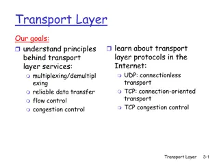
TCP Congestion Control in Computer Networks
Explore the principles, causes, costs, and approaches towards TCP congestion control in computer networks. Learn about network-assisted and end-end congestion control approaches. Lecture material from "Computer Networks: A Systems Approach."

Download Presentation

Please find below an Image/Link to download the presentation.
The content on the website is provided AS IS for your information and personal use only. It may not be sold, licensed, or shared on other websites without obtaining consent from the author. If you encounter any issues during the download, it is possible that the publisher has removed the file from their server.
You are allowed to download the files provided on this website for personal or commercial use, subject to the condition that they are used lawfully. All files are the property of their respective owners.
The content on the website is provided AS IS for your information and personal use only. It may not be sold, licensed, or shared on other websites without obtaining consent from the author.
E N D
Presentation Transcript
TCP Congestion Control Computer Networks
Principles of Congestion Control Congestion: informally: too many sources sending too much data too fast for the networkto handle different from flow control! manifestations: lost packets (buffer overflow at routers) long delays (queueing in router buffers) a major problem in networking! 2 Computer Networks TCP Congestion Control
Causes/Costs of Congestion Scenario 1 Host A out in : original data two senders, two receivers one router, infinite buffers no retransmission unlimited shared output link buffers Host B large delays when congested maximum achievable throughput 3 Computer Networks TCP Congestion Control
Causes/Costs of Congestion Scenario 2 one router, finite buffers sender retransmits lost packets offered load Host A out in : original data 'in : original data, plus retransmitted data Host B finite shared output link buffers 4 Computer Networks TCP Congestion Control
Causes/Costs of Congestion Scenario 2 out always: (goodput) in = out in > perfect retransmission only when loss: in retransmission of delayed (not lost) packet makes larger (than perfect case) for same out R/2 R/2 R/2 R/3 out out out R/4 R/2 R/2 R/2 in in in a. b. c. costs of congestion: more work (retransmissions) for a given goodput unneeded retransmissions: link carries multiple copies of packet 5 Computer Networks TCP Congestion Control
Approaches towards Congestion Control Two broad approaches towards congestion control: network-assisted congestion control: routers provide feedback to end systems single bit indicating congestion (SNA, DECbit, TCP/IP ECN, ATM) explicit rate sender should use for sending. end-end congestion control: no explicit feedback from network congestion inferred from end-system observed loss, delay approach taken by TCP 6 Computer Networks TCP Congestion Control
TCP Congestion Control Lecture material taken from Computer Networks A Systems Approach , Fourth Edition,Peterson and Davie, Morgan Kaufmann, 2007. Advanced Computer Networks
TCP Congestion Control Essential strategy :: The TCP host sends packets into the network without a reservation and then the host reacts to observable events. Originally TCP assumed FIFO queuing. Basic idea :: each source determines how much capacity is available to a given flow in the network. ACKs are used to pace the transmission of packets such that TCP is self-clocking . 8 Computer Networks TCP Congestion Control
TCP Congestion Control K & R Goal:TCP sender should transmit as fast as possible, but without congesting network. issue - how to find rate justbelow congestion level? Each TCP sender sets its window size, based on implicit feedback: ACK segment received network is not congested, so increase sending rate. lost segment - assume loss due to congestion, so decrease sending rate. 9 Computer Networks TCP Congestion Control
TCP Congestion Control K & R probing for bandwidth : increase transmission rate on receipt of ACK, until eventually loss occurs, then decrease transmission rate continue to increase on ACK, decrease on loss (since available bandwidth is changing, depending on other connections in network). ACKs being received, so increase rate X loss, so decrease rate X X X sending rate TCP s X sawtooth behavior time Q: how fast to increase/decrease? 10 Computer Networks TCP Congestion Control
AIMD (Additive Increase / Multiplicative Decrease) CongestionWindow (cwnd) is a variable held by the TCP source for each connection. MaxWindow :: min (CongestionWindow , AdvertisedWindow) EffectiveWindow = MaxWindow (LastByteSent -LastByteAcked) cwnd is set based on the perceived level of congestion. The Host receives implicit (packet drop) or explicit (packet mark) indications of internal congestion. 11 Computer Networks TCP Congestion Control
Additive Increase (AI) Additive Increase is a reaction to perceived available capacity (referred to as congestion avoidance stage). Frequently in the literature, additive increase is defined by parameter (where the default is = 1). Linear Increase :: For each cwnd s worth of packets sent, increase cwnd by 1 packet. In practice, cwnd is incremented fractionally for each arriving ACK. increment = MSS x (MSS /cwnd) cwnd = cwnd + increment 12 Computer Networks TCP Congestion Control
Source Destination Add one packet each RTT Figure 6.8 Additive Increase 13 Computer Networks TCP Congestion Control
Multiplicative Decrease (MD) * Key assumption :: a dropped packet and resultant timeout are due to congestion at a router. Frequently in the literature, multiplicative decrease is defined by parameter (where the default is = 0.5) Multiplicate Decrease:: TCP reacts to a timeout by halving cwnd. Although defined in bytes, the literature often discusses cwnd in terms of packets (or more formally in MSS == Maximum Segment Size). cwnd is not allowed below the size of a single packet. 14 Computer Networks TCP Congestion Control
AIMD (Additive Increase / Multiplicative Decrease) It has been shown that AIMD is a necessary condition for TCP congestion control to be stable. Because the simple CC mechanism involves timeouts that cause retransmissions, it is important that hosts have an accurate timeout mechanism. Timeouts set as a function of average RTT and standard deviation of RTT. However, TCP hosts only sample round-trip time once per RTT using coarse-grained clock. 15 Computer Networks TCP Congestion Control
70 60 50 40 30 20 10 1.0 2.0 3.0 4.0 5.0 6.0 7.0 8.0 9.0 10.0 Time (seconds) Figure 6.9 Typical TCP Sawtooth Pattern 16 Computer Networks TCP Congestion Control
Slow Start Linear additive increase takes too long to ramp up a new TCP connection from cold start. Beginning with TCP Tahoe, the slow start mechanism was added to provide an initial exponential increase in the size ofcwnd. Remember mechanism by: slow start prevents a slow start. Moreover, slow start is slower than sending a full advertised window s worth of packets all at once. 17 Computer Networks TCP Congestion Control
Slow Start The source starts with cwnd = 1. Every time an ACK arrives, cwnd is incremented. cwnd is effectively doubled per RTT epoch . Two slow start situations: At the very beginning of a connection {cold start}. When the connection goes dead waiting for a timeout to occur (i.e, when the advertized window goes to zero!) 18 Computer Networks TCP Congestion Control
Source Destination Slow Start Add one packet per ACK Figure 6.10 Slow Start 19 Computer Networks TCP Congestion Control
Slow Start However, in the second case the source has more information. The current value of cwnd can be saved as a congestion threshold. This is also known as the slow start threshold ssthresh. 20 Computer Networks TCP Congestion Control
ssthresh 21 Computer Networks TCP Congestion Control
70 60 50 40 30 20 10 1.0 2.0 3.0 4.0 5.0 6.0 7.0 8.0 9.0 Time (seconds) Figure 6.11 Behavior of TCP Congestion Control 22 Computer Networks TCP Congestion Control
Fast Retransmit Coarse timeouts remained a problem, and Fast retransmit was added with TCP Tahoe. Since the receiver responds every time a packet arrives, this implies the sender will see duplicate ACKs. Basic Idea:: use duplicate ACKs to signal lost packet. Fast Retransmit Upon receipt of three duplicate ACKs, the TCP Sender retransmits the lost packet. 23 Computer Networks TCP Congestion Control
Fast Retransmit Generally, fast retransmit eliminates abouthalf the coarse-grain timeouts. This yields roughly a 20% improvement in throughput. Note fast retransmit does not eliminate all the timeouts due to small window sizes at the source. 24 Computer Networks TCP Congestion Control
Sender Receiver Packet 1 Packet 2 Packet 3 Packet 4 ACK 1 ACK 2 Fast Retransmit ACK 2 Packet 5 Packet 6 ACK 2 ACK 2 Based on three duplicate ACKs Retransmit packet 3 ACK 6 Figure 6.12 Fast Retransmit 25 Computer Networks TCP Congestion Control
70 60 50 40 30 20 10 1.0 2.0 3.0 4.0 5.0 6.0 7.0 Time (seconds) Figure 6.13 TCP Fast Retransmit Trace 26 Computer Networks TCP Congestion Control
Fast Recovery Fast recovery was added with TCP Reno. Basic idea:: When fast retransmit detects three duplicate ACKs, start the recovery process from congestion avoidance region and use ACKs in the pipe to pace the sending of packets. Fast Recovery After Fast Retransmit, half cwnd and commence recovery from this point using linear additive increase primed by left over ACKs in pipe. 27 Computer Networks TCP Congestion Control
Modified Slow Start With fast recovery, slow start only occurs: At cold start After a coarse-grain timeout This is the difference between TCP Tahoe and TCP Reno!! 28 Computer Networks TCP Congestion Control
Many TCP flavors TCP New Reno TCP SACK requires sender and receiver both to support TCP SACK. possible state machine is complex. TCP Vegas adjusts window size based on difference between expected and actual RTT. TCP BIC TCP Cubic {used by Linux} TCP Compound {used by Windows} 29 Computer Networks TCP Congestion Control
TCP New Reno Two problem scenarios with TCP Reno bursty losses, Reno cannot recover from bursts of 3+ losses. Packets arriving out-of-order can yield duplicate acks when in fact there is no loss. New Reno solution try to determine the end of a burst loss. 30 Computer Networks TCP Congestion Control
TCP New Reno When duplicate ACKs trigger a retransmission for a lost packet, remember the highest packet sent from window in recover. Upon receiving an ACK, if ACK < recover => partial ACK If ACK recover => new ACK 31 Computer Networks TCP Congestion Control
TCP New Reno Partial ACK implies another lost packet: retransmit next packet, inflate window and stay in fast recovery. New ACK implies fast recovery is over: starting from 0.5 x cwnd proceed with congestion avoidance (linear increase). New Reno recovers from n losses in n round trips. 32 Computer Networks TCP Congestion Control
Figure 5.6 Three-way TCP Handshake 33 Computer Networks TCP Congestion Control
Adaptive Retransmissions RTT:: Round Trip Time between a pair of hosts on the Internet. How to set the TimeOut value (RTO)? The timeout value is set as a function of the expected RTT. Consequences of a bad choice? 34 Computer Networks TCP Congestion Control
Original Algorithm Keep a running average of RTT and compute TimeOut as a function of this RTT. Send packet and keep timestamp ts . When ACK arrives, record timestamp ta . SampleRTT = ta - ts 35 Computer Networks TCP Congestion Control
Original Algorithm Compute a weighted average: EstimatedRTT = xEstimatedRTT + (1- ) x SampleRTT Original TCP spec: in range (0.8,0.9) TimeOut = 2 x EstimatedRTT 36 Computer Networks TCP Congestion Control
Karn/Partidge Algorithm An obvious flaw in the original algorithm: Whenever there is a retransmission it is impossible to know whether to associate the ACK with the original packet or the retransmitted packet. 37 Computer Networks TCP Congestion Control
Figure 5.10 Associating the ACK? Sender Receiver Sender Receiver Original transmission Retransmission Original transmission ACK Retransmission ACK (a) (b) 38 Computer Networks TCP Congestion Control
Karn/Partidge Algorithm 1. Do not measure SampleRTT when sending packet more than once. 2. For each retransmission, set TimeOut to double the last TimeOut. { Note this is a form of exponential backoff based on the believe that the lost packet is due to congestion.} 39 Computer Networks TCP Congestion Control
Jacobson/Karels Algorithm The problem with the original algorithm is that it did not take into account the variance of SampleRTT. Difference = SampleRTT EstimatedRTT EstimatedRTT = EstimatedRTT + ( x Difference) Deviation = (|Difference| - Deviation) where is a fraction between 0 and 1. 40 Computer Networks TCP Congestion Control
Jacobson/Karels Algorithm TCP computes timeout using both the mean and variance of RTT TimeOut = x EstimatedRTT + x Deviation where based on experience = 1 and = 4. 41 Computer Networks TCP Congestion Control
TCP Congestion Control Summary Congestion occurs due to a variety of circumstance. TCP interacts with routers in the subnet and reacts to implicit congestion notification (packet drop) by reducing the TCP sender s congestion window (MD). TCP increases congestion window using slow start or congestion avoidance (AI). 42 Computer Networks TCP Congestion Control
TCP Congestion Control Summary Important TCP Congestion Control ideas include: AIMD, Slow Start, Fast Retransmit and Fast Recovery. Currently, the two most common versions of TCP are Compound (Windows) and Cubic (Linux). TCP needs rules and an algorithm to determine RIO and RTO. 43 Computer Networks TCP Congestion Control


")

")