TCP Connection and Segment Structure
Explore the sequence numbers for segments in a TCP connection transferring a file, with insights into TCP segment format, control fields, flags, and window size, providing a comprehensive overview of TCP protocol operations.

Download Presentation

Please find below an Image/Link to download the presentation.
The content on the website is provided AS IS for your information and personal use only. It may not be sold, licensed, or shared on other websites without obtaining consent from the author. If you encounter any issues during the download, it is possible that the publisher has removed the file from their server.
You are allowed to download the files provided on this website for personal or commercial use, subject to the condition that they are used lawfully. All files are the property of their respective owners.
The content on the website is provided AS IS for your information and personal use only. It may not be sold, licensed, or shared on other websites without obtaining consent from the author.
E N D
Presentation Transcript
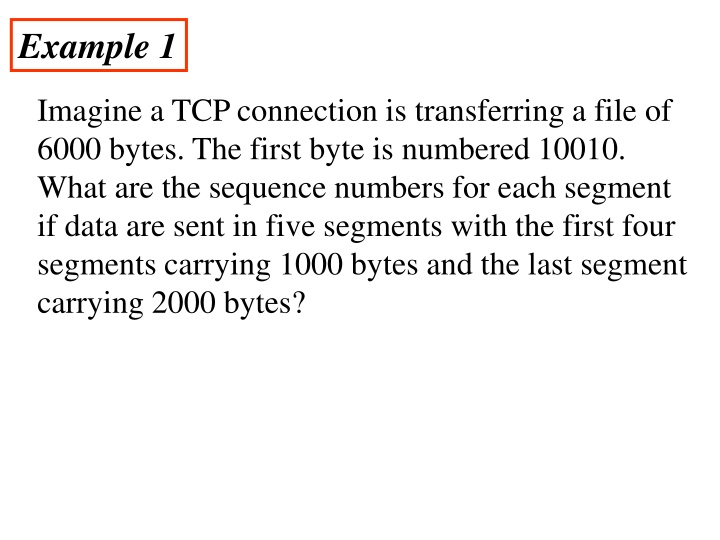
Example 1 Imagine a TCP connection is transferring a file of 6000 bytes. The first byte is numbered 10010. What are the sequence numbers for each segment if data are sent in five segments with the first four segments carrying 1000 bytes and the last segment carrying 2000 bytes?
Solution The following shows the sequence number for each segment: Segment 1 ==> sequence number: 10,010 (range: 10,010 to 11,009) Segment 2 ==> sequence number: 11,010 (range: 11,010 to 12,009) Segment 3 ==> sequence number: 12,010 (range: 12,010 to 13,009) Segment 4 ==> sequence number: 13,010 (range: 13,010 to 14,009) Segment 5 ==> sequence number: 14,010 (range: 14,010 to 16,009)
The segment consists of a 20- to 60-byte header, followed by data from the application program. The header is 20 bytes if there are no options and up to 60 bytes if it contains options.
Reserved: This is a 6-bit field reserved for future use. Control: This field defines 6 different control bits or flags. One or more of these bits can be set at a time. These bits enable flow control, connection establishment and termination, connection abortion, and the mode of data transfer in TCP.
Description of flags in the control field Flag Description URG The value of the urgent pointer field is valid. ACK The value of the acknowledgment field is valid. PSH Push the data. RST The connection must be reset. Synchronize sequence numbers during connection. SYN FIN Terminate the connection.
Window size: This field defines the size of the window, in bytes, that the other party must maintain. The length of this field is 16 bits, which means that the maximum size of the window is 65,535 bytes. This value is normally referred to as the receiving window (rwnd) and is determined by the receiver. The sender must obey the dictation of the receiver in this case.
Checksum: This 16-bit field contains the checksum. The calculation of the checksum for TCP follows the same procedure as the one described for UDP. However, the inclusion of the checksum in the UDP datagram is optional, whereas the inclusion of the checksum for TCP is mandatory. The same pseudoheader, serving the same purpose, is added to the segment. For the TCP pseudoheader, the value for the protocol field is 6.
Urgent pointer: This l6-bit field, which is valid only if the urgent flag is set, is used when the segment contains urgent data. Options: There can be up to 40 bytes of optional information in the TCP header.
A TCP Connection The point is that a TCP connection is virtual, not physical. TCP operates at a higher level. TCP uses the services of IP to deliver individual segments to the receiver, but it controls the connection itself. If a segment is lost or corrupted, it is retransmitted. Unlike TCP, IP is unaware of this retransmission. If a segment arrives out of order, TCP holds it until the missing segments arrive; IP is unaware of this reordering.
Typical TCP Transaction A TCP Transaction consists of 3 Phases 1. Connection Establishment Handshaking between client and server 2. Reliable, In-Order Data Exchange Recover any lost data through retransmissions and ACKs 3. Connection Termination Closing the connection Server Client Connection Establishment Reliable, In-Order Data Exchange Connection Termination time time
In TCP, connection-oriented transmission requires three phases: 1] connection establishment. 2] data transfer and 3] connection termination.
1] connection establishment Three-Way Handshaking Simultaneous Open
Connection establishment using three-way handshaking
The server program tells its TCP that it is ready to accept a connection. This is called a request for a passive open. Although the server TCP is ready to accept any connection from any machine in the world, it cannot make the connection itself. The client program issues a request for an active open. A client that wishes to connect to an open server tells its TCP that it needs to be connected to that particular server.
1] The client sends the first segment, a SYN segment, in which only the SYN flag is set. This segment is for synchronization of sequence numbers. It consumes one sequence number. When the data transfer starts, the sequence number is incremented by 1. We can say that the SYN segment carries no real data, but we can think of it as containing 1 imaginary byte.
2] The server sends the second segment, a SYN +ACK segment, with 2 flag bits set: SYN and ACK. This segment has a dual purpose. It is a SYN segment for communication in the other direction and serves as the acknowledgment for the SYN segment. It consumes one sequence number.
3] The client sends the third segment. This is just an ACK segment. It acknowledges the receipt of the second segment with the ACK flag and acknowledgment number field. Note that the sequence number in this segment is the same as the one in the SYN segment; the ACK segment does not consume any sequence numbers.
Connection establishment using Simultaneous Open A rare situation, called a simultaneous open, may occur when both processes issue an active open. In this case, both TCPs transmit a SYN + ACK segment to each other, and one single connection is established between them.
Data transfer After connection is established, bidirectional data transfer can take place. The client and server can both send data and acknowledgments. It is enough to know that data traveling in the same direction as an acknowledgment are carried on the same segment. The acknowledgment is piggybacked with the data.
The data segments sent by the client have the PSH (push) flag set. so that the server TCP knows to deliver data to the server process as soon as they are received. The segment from the server, on the other hand, does not set the push flag. Most TCP implementations have the option to set or not set this flag.
3] Connection termination Any of the two parties involved in exchanging data (client or server) can close the connection, although it is usually initiated by the client. Two options for connection termination: A] Three-way handshaking and B] Four-way handshaking with a half-close option.
Connection termination using three-way handshaking
1] In a normal situation, the client TCP, after receiving a close command from the client process, sends the first segment, a FIN segment in which the FIN flag is set. Note that a FIN segment can include the last chunk of data sent by the client, or it can be just a control segment . If it is only a control segment, it consumes only one sequence number.
2] The server TCP, after receiving the FIN segment, informs its process of the situation and sends the second segment, a FIN +ACK segment, to confirm the receipt of the FIN segment from the client and at the same time to announce the closing of the connection in the other direction. This segment can also contain the last chunk of data from the server. If it does not carry data, it consumes only one sequence number.
3] The client TCP sends the last segment, an ACK segment, to confirm the receipt of the FIN segment from the TCP server. This segment contains the acknowledgment number, which is 1 plus the sequence number received in the FIN segment from the server. This segment cannot carry data and consumes no sequence numbers.
B] Four-way handshaking with a half- close option. Half-Close In TCP, one end can stop sending data while still receiving data. This is called a half- close. Although either end can issue a half-close, it is normally initiated by the client. It can occur when the server needs all the data before processing can begin.
A good example is sorting. When the client sends data to the server to be sorted, the server needs to receive all the data before sorting can start. This means the client, after sending all the data, can close the connection in the outbound direction. However, the inbound direction must remain open to receive the sorted data. The server, after receiving the data, still needs time for sorting; its outbound direction must remain open.
The client half-closes the connection by sending a FIN segment. The server accepts the half-close by sending the ACK segment. The data transfer from the client to the server stops. The server, however, can still send data. When the server has sent all the processed data, it sends a FIN segment, which is acknowledged by an ACK from the client. After half-closing of the connection, data can travel from the server to the client and acknowledgments can travel from the client to the server.
The client cannot send any more data to the server. Note the sequence numbers we have used. The second segment (ACK) consumes no sequence number. Although the client has received sequence number y - 1 and is expecting y, the server sequence number is still y - 1. When the connection finally closes, the sequence number of the last ACK segment is still x, because no sequence numbers are consumed during data transfer in that direction.
TCP Flow Control TCP uses a sliding window, to handle flow control. The sliding window protocol used by TCP, however, is something between the Go-Back-N and Selective Repeat sliding window. The sliding window protocol in TCP looks like the Go-Back-N protocol because it does not use NAKs; it looks like Selective Repeat because the receiver holds the out-of-order segments until the missing ones arrive.
Opening a window means moving the right wall to the right. This allows more new bytes in the buffer that are eligible for sending. Closing the window means moving the left wall to the right. This means that some bytes have been acknowledged and the sender need not worry about them anymore.
Shrinking the window means moving the right wall to the left. This is strongly discouraged and not allowed in some implementations. because it means revoking the eligibility of some bytes for sending. This is a problem if the sender has already sent these bytes. Note that the left wall cannot move to the left because this would revoke some of the previously sent acknowledgments.
The size of the window at one end is determined by the lesser of two values: receiver window (rwnd) or congestion window (cwnd). The receiver window is the value advertised by the opposite end in a segment containing acknowledgment. It is the number of bytes the other end can accept before its buffer overflows and data are discarded. The congestion window is a value determined by the network to avoid congestion.
RTP Real-time Transport Protocol (RTP) is the protocol designed to handle real-time traffic on the Internet. RTP does not have a delivery mechanism; it must be used with UDP. RTP stands between UDP and the application program. The main contributions of RTP are time-stamping, sequencing, facilities. and mixing
The Real-time Transport Protocol a network protocol for delivering audio and video over IP networks. (RTP) is RTP is used extensively in communication and entertainment systems that involve streaming media, such as telephony, video teleconference applications, television services .
2] P:- This 1-bit field, if set to 1, indicates the presence of padding at the end of the packet. In this case, the value of the last byte in the padding defines the length of the padding. There is no padding if the value of the P field is O.
3] X: - This 1-bit field, if set to 1, indicates an extra extension header between the basic header and the data. There is no extra extension header if the value of this field is O. 4] Contributor count :- This 4-bit field indicates the number of contributors. Note that we can have a maximum of 16 contributors because a 4-bit field only allows a number between 0 and 15.
5] M: - This 1-bit field is a marker used by the application to indicate, for example, the end of its data. 6] Payload type :- This 7-bit field indicates the type of the payload.
7] Sequence number :- This field is 16 bits in length. It is used to number the RTP packets. The sequence number of the first packet is chosen randomly; it is incremented by 1 for each subsequent packet. The sequence number is used by the receiver to detect lost or out-of-order packets. 8] Timestamp :- This is a 32-bit field that indicates the time relationship between packets. The timestamp for the first packet is a random number.
9] Synchronization source identifier:- If there is only one source, this 32-bit field defines the source. However, if there are several sources, the mixer is the synchronization source and the other sources are contributors. The value of the source identifier is a random number chosen by the source. The protocol provides a strategy in case of conflict (two sources start with the same sequence number).
10] Contributor identifier: - Each of these 32-bit identifiers defines a source. When there is more than one source in a session, the mixer is the synchronization source and the remaining sources are the contributors.