TCP Reliable Data Transfer and Retransmission Scenarios Explained
Explore the intricate workings of TCP reliable data transfer, including multiplexing, connection management, flow control, and retransmission scenarios. Dive into the principles of congestion control and the role of UDP and TCP in the transport layer.

Download Presentation

Please find below an Image/Link to download the presentation.
The content on the website is provided AS IS for your information and personal use only. It may not be sold, licensed, or shared on other websites without obtaining consent from the author. If you encounter any issues during the download, it is possible that the publisher has removed the file from their server.
You are allowed to download the files provided on this website for personal or commercial use, subject to the condition that they are used lawfully. All files are the property of their respective owners.
The content on the website is provided AS IS for your information and personal use only. It may not be sold, licensed, or shared on other websites without obtaining consent from the author.
E N D
Presentation Transcript
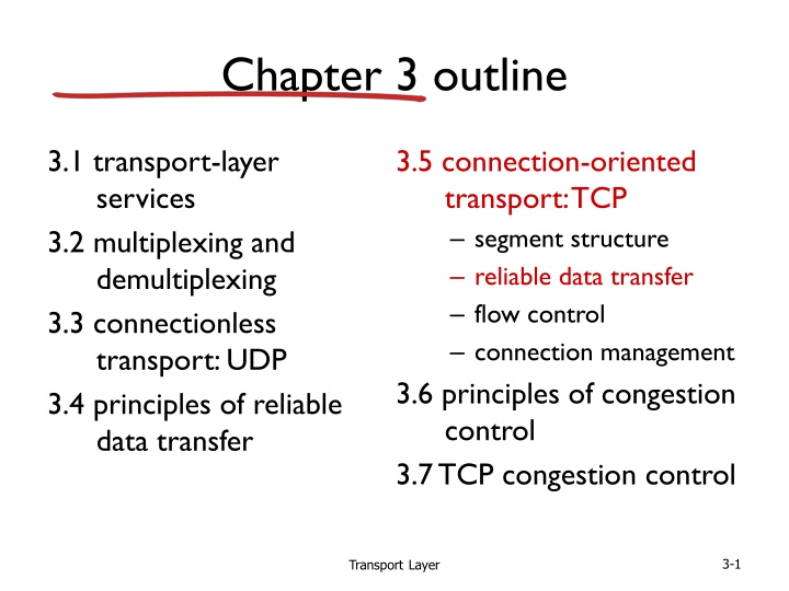
Chapter 3 outline 3.1 transport-layer services 3.2 multiplexing and demultiplexing 3.3 connectionless transport: UDP 3.4 principles of reliable data transfer 3.5 connection-oriented transport: TCP segment structure reliable data transfer flow control connection management 3.6 principles of congestion control 3.7 TCP congestion control TransportLayer 3-1
TCP reliable data transfer TCP creates rdt service on top of IP s unreliable service pipelined segments cumulative acks single retransmission timer retransmissions triggered by: timeout events duplicate acks let s initially consider simplified TCP sender: ignore duplicate acks ignore flow control, congestion control TransportLayer 3-2
TCP sender events: data rcvd from app: create segment with seq # seq # is byte-stream number of first data byte in segment start timer if not already running think of timer as for oldest unacked segment expiration interval: TimeOutInterval timeout: retransmit segment that caused timeout restart timer ack rcvd: if ack acknowledges previously unacked segments update what is known to be ACKed start timer if there are still unacked segments TransportLayer 3-3
TCP sender (simplified) data received from application above create segment, seq. #: NextSeqNum pass segment to IP (i.e., send ) NextSeqNum = NextSeqNum + length(data) if (timer currently not running) start timer wait for event NextSeqNum = InitialSeqNum SendBase = InitialSeqNum timeout retransmit not-yet-acked segment with smallest seq. # start timer ACK received, with ACK field value y if (y > SendBase) { SendBase = y /* SendBase 1: last cumulatively ACKed byte */ if (there are currently not-yet-acked segments) start timer else stop timer } TransportLayer 3-4
TCP: retransmission scenarios Host B Host B Host A Host A SendBase=92 Seq=92, 8 bytes of data Seq=92, 8 bytes of data Seq=100, 20 bytes of data timeout timeout ACK=100 X ACK=100 ACK=120 Seq=92, 8 bytes of data Seq=92, 8 bytes of data SendBase=100 SendBase=120 ACK=100 ACK=120 SendBase=120 lost ACK scenario premature timeout TransportLayer 3-5
TCP: retransmission scenarios Host B Host A Seq=92, 8 bytes of data Seq=100, 20 bytes of data ACK=100 timeout X ACK=120 Seq=120, 15 bytes of data cumulative ACK TransportLayer 3-6
TCP ACK generation[RFC 1122, RFC 2581] TCP receiver action event at receiver delayed ACK. Wait up to 500ms for next segment. If no next segment, send ACK arrival of in-order segment with expected seq #. All data up to expected seq # already ACKed immediately send single cumulative ACK, ACKing both in-order segments arrival of in-order segment with expected seq #. One other segment has ACK pending immediately send duplicate ACK, indicating seq. # of next expected byte arrival of out-of-order segment higher-than-expect seq. # . Gap detected immediate send ACK, provided that segment starts at lower end of gap arrival of segment that partially or completely fills gap TransportLayer 3-7
TCP fast retransmit time-out period often relatively long: long delay before resending lost packet detect lost segments via duplicate ACKs. sender often sends many segments back- to-back if segment is lost, there will likely be many duplicate ACKs. TCP fast retransmit if sender receives 3 ACKs for same data ( triple duplicate ACKs ), resend unacked segment with smallest seq # likely that unacked segment lost, so don t wait for timeout ( triple duplicate ACKs ), TransportLayer 3-8
TCP fast retransmit Host B Host A Seq=92, 8 bytes of data Seq=100, 20 bytes of data X ACK=100 timeout ACK=100 ACK=100 ACK=100 Seq=100, 20 bytes of data fast retransmit after sender receipt of triple duplicate ACK TransportLayer 3-9
Chapter 3 outline 3.1 transport-layer services 3.2 multiplexing and demultiplexing 3.3 connectionless transport: UDP 3.4 principles of reliable data transfer 3.5 connection-oriented transport: TCP segment structure reliable data transfer flow control connection management 3.6 principles of congestion control 3.7 TCP congestion control TransportLayer 3-10
TCP flow control application process application may remove data from TCP socket buffers . application OS TCP socket receiver buffers slower than TCP receiver is delivering (sender is sending) TCP code IP code flow control receiver controls sender, so sender won t overflow receiver s buffer by transmitting too much, too fast from sender receiver protocol stack TransportLayer 3-11
TCP flow control receiver advertises free buffer space by including rwnd value in TCP header of receiver-to-sender segments RcvBuffer size set via socket options (typical default is 4096 bytes) many operating systems autoadjust RcvBuffer sender limits amount of unacked ( in-flight ) data to receiver s rwnd value guarantees receive buffer will not overflow to application process buffered data RcvBuffer free buffer space rwnd TCP segment payloads receiver-side buffering TransportLayer 3-12
Chapter 3 outline 3.1 transport-layer services 3.2 multiplexing and demultiplexing 3.3 connectionless transport: UDP 3.4 principles of reliable data transfer 3.5 connection-oriented transport: TCP segment structure reliable data transfer flow control connection management 3.6 principles of congestion control 3.7 TCP congestion control TransportLayer 3-13
Connection Management before exchanging data, sender/receiver handshake : agree to establish connection (each knowing the other willing to establish connection) agree on connection parameters application application connection state: ESTAB connection variables: seq # client-to-server server-to-client rcvBuffer size at server,client network connection state: ESTAB connection Variables: seq # client-to-server server-to-client rcvBuffer size at server,client network Socket clientSocket = newSocket("hostname","port number"); Socket connectionSocket = welcomeSocket.accept(); TransportLayer 3-14
Agreeing to establish a connection 2-way handshake: Q: will 2-way handshake always work in network? variable delays retransmitted messages (e.g. req_conn(x)) due to message loss message reordering can t see other side Let s talk ESTAB OK ESTAB choose x req_conn(x) ESTAB acc_conn(x) ESTAB TransportLayer 3-15
Agreeing to establish a connection 2-way handshake failure scenarios: choose x choose x req_conn(x) req_conn(x) ESTAB ESTAB retransmit req_conn(x) retransmit req_conn(x) acc_conn(x) acc_conn(x) ESTAB ESTAB data(x+1) accept data(x+1) req_conn(x) retransmit data(x+1) connection x completes connection x completes client server forgets x server forgets x client terminates terminates req_conn(x) ESTAB accept data(x+1) ESTAB data(x+1) half open connection! (no client!) TransportLayer 3-16
TCP 3-way handshake client state server state LISTEN LISTEN choose init seq num, x send TCP SYN msg SYNSENT SYNbit=1, Seq=x choose init seq num, y send TCP SYNACK msg, acking SYN SYN RCVD SYNbit=1, Seq=y ACKbit=1; ACKnum=x+1 received SYNACK(x) indicates server is live; send ACK for SYNACK; this segment may contain client-to-server data ESTAB ACKbit=1, ACKnum=y+1 received ACK(y) indicates client is live ESTAB TransportLayer 3-17
TCP 3-way handshake: FSM closed Socket connectionSocket = welcomeSocket.accept(); Socket clientSocket = newSocket("hostname","port number"); SYN(x) SYNACK(seq=y,ACKnum=x+1) create new socket for communication back to client SYN(seq=x) listen SYN sent SYN rcvd SYNACK(seq=y,ACKnum=x+1) ACK(ACKnum=y+1) ESTAB ACK(ACKnum=y+1) TransportLayer 3-18
TCP: closing a connection client, server each close their side of connection send TCP segment with FIN bit = 1 respond to received FIN with ACK on receiving FIN, ACK can be combined with own FIN simultaneous FIN exchanges can be handled TransportLayer 3-19
TCP: closing a connection client state server state ESTAB ESTAB clientSocket.close() FINbit=1, seq=x FIN_WAIT_1 can no longer send but can receive data CLOSE_WAIT ACKbit=1; ACKnum=x+1 can still send data wait for server FIN_WAIT_2 close LAST_ACK FINbit=1, seq=y can no longer send data TIMED_WAIT ACKbit=1; ACKnum=y+1 timed wait for 2*max segment lifetime CLOSED CLOSED TransportLayer 3-20
Chapter 3 outline 3.1 transport-layer services 3.2 multiplexing and demultiplexing 3.3 connectionless transport: UDP 3.4 principles of reliable data transfer 3.5 connection-oriented transport: TCP segment structure reliable data transfer flow control connection management 3.6 principles of congestion control 3.7 TCP congestion control TransportLayer 3-21
Principles of congestion control congestion: informally: too many sources sending too much data too fast for network to handle different from flow control! manifestations: lost packets (buffer overflow at routers) long delays (queueing in router buffers) a top-10 problem! TransportLayer 3-22
Causes/costs of congestion: scenario 1 original data: in throughput: out two senders, two receivers one router, infinite buffers output link capacity: R no retransmission Host A unlimited shared output link buffers Host B R/2 delay out in in R/2 R/2 large delays as arrival rate, in, approaches capacity maximum per-connection throughput: R/2 TransportLayer 3-23
Causes/costs of congestion: scenario 2 one router, finite buffers sender retransmission of timed-out packet application-layer input = application-layer output: in = out transport-layer input includes retransmissions : in in in: original data 'in:original data, plus retransmitted data out Host A finite shared output link buffers Host B TransportLayer 3-24
Causes/costs of congestion: scenario 2 R/2 idealization: perfect knowledge sender sends only when router buffers available out in R/2 in: original data 'in:original data, plus retransmitted data out copy A free buffer space! finite shared output link buffers Host B TransportLayer 3-25
Causes/costs of congestion: scenario 2 Idealization: known loss packets can be lost, dropped at router due to full buffers sender only resends if packet known to be lost in: original data 'in:original data, plus retransmitted data out copy A no buffer space! Host B TransportLayer 3-26
Causes/costs of congestion: scenario 2 Idealization: known loss packets can be lost, dropped at router due to full buffers sender only resends if packet known to be lost R/2 when sending at R/2, some packets are retransmissions but asymptotic goodput is still R/2 (why?) out R/2 in in: original data 'in:original data, plus retransmitted data out A free buffer space! Host B TransportLayer 3-27
Causes/costs of congestion: scenario 2 Realistic: duplicates packets can be lost, dropped at router due to full buffers sender times out prematurely, sending two copies, both of which are delivered R/2 when sending at R/2, some packets are retransmissions including duplicated that are delivered! out R/2 in in 'in out copy timeout A free buffer space! Host B TransportLayer 3-28
Causes/costs of congestion: scenario 2 Realistic: duplicates packets can be lost, dropped at router due to full buffers sender times out prematurely, sending two copies, both of which are delivered R/2 when sending at R/2, some packets are retransmissions including duplicated that are delivered! out R/2 in costs of congestion: more work (retrans) for given goodput unneeded retransmissions: link carries multiple copies of pkt decreasing goodput TransportLayer 3-29
Causes/costs of congestion: scenario 3 Q: what happens as in and in increase ? A: as red in increases, all arriving blue pkts at upper queue are dropped, blue throughput 0 four senders multihop paths timeout/retransmit out Host A in: original data 'in:original data, plus retransmitted data Host B finite shared output link buffers Host D Host C TransportLayer 3-30
Causes/costs of congestion: scenario 3 C/2 out in C/2 another cost of congestion: when packet dropped, any upstream transmission capacity used for that packet was wasted! TransportLayer 3-31
Approaches towards congestion control two broad approaches towards congestion control: end-end congestion control: no explicit feedback from network congestion inferred from end-system observed loss, delay approach taken by TCP network-assisted congestion control: routers provide feedback to end systems single bit indicating congestion (SNA, DECbit, TCP/IP ECN, ATM) explicit rate for sender to send at TransportLayer 3-32
Case study: ATM ABR congestion control ABR: available bit rate: elastic service if sender s path underloaded : sender should use available bandwidth if sender s path congested: sender throttled to minimum guaranteed rate RM (resource management) cells: sent by sender, interspersed with data cells bits in RM cell set by switches ( network-assisted ) NI bit: no increase in rate (mild congestion) CI bit: congestion indication RM cells returned to sender by receiver, with bits intact TransportLayer 3-33
Case study: ATM ABR congestion control RM cell data cell two-byte ER (explicit rate) field in RM cell congested switch may lower ER value in cell senders send rate thus max supportable rate on path EFCI bit in data cells: set to 1 in congested switch if data cell preceding RM cell has EFCI set, receiver sets CI bit in returned RM cell TransportLayer 3-34
Chapter 3 outline 3.1 transport-layer services 3.2 multiplexing and demultiplexing 3.3 connectionless transport: UDP 3.4 principles of reliable data transfer 3.5 connection-oriented transport: TCP segment structure reliable data transfer flow control connection management 3.6 principles of congestion control 3.7 TCP congestion control TransportLayer 3-35
TCP congestion control: additive increase multiplicative decrease approach: senderincreases transmission rate (window size), probing for usable bandwidth, until loss occurs additive increase: increase cwndby 1 MSS every RTT until loss detected multiplicative decrease: cut cwnd in half after loss additively increase window size . until loss occurs (then cut window in half) congestion window size cwnd: TCP sender AIMD saw tooth behavior: probing for bandwidth time TransportLayer 3-36
TCP Congestion Control: details sender sequence number space TCP sending rate: roughly: send cwnd bytes, wait RTT for ACKS, then send more bytes rate~~ RTT cwnd last byte ACKed last byte sent sent, not- yet ACKed ( in- flight ) cwnd bytes/sec sender limits transmission: LastByteSent- LastByteAcked < cwnd cwnd is dynamic, function of perceived network congestion TransportLayer 3-37
TCP Slow Start Host B Host A when connection begins, increase rate exponentially until first loss event: initially cwnd = 1 MSS double cwnd every RTT done by incrementing cwnd for every ACK received summary: initial rate is slow but ramps up exponentially fast RTT time TransportLayer 3-38
TCP: detecting, reacting to loss loss indicated by timeout: cwnd set to 1 MSS; window then grows exponentially (as in slow start) to threshold, then grows linearly loss indicated by 3 duplicate ACKs: TCP RENO dup ACKs indicate network capable of delivering some segments cwnd is cut in half window then grows linearly TCP Tahoe always sets cwnd to 1 (timeout or 3 duplicate acks) TransportLayer 3-39
TCP: switching from slow start to CA Q: when should the exponential increase switch to linear? A: when cwnd gets to 1/2 of its value before timeout. Implementation: variable ssthresh on loss event, ssthresh is set to 1/2 of cwndjust before loss event TransportLayer 3-40
Summary: TCP Congestion Control New ACK! New ACK! new ACK. duplicate ACK cwnd = cwnd + MSS (MSS/cwnd) dupACKcount = 0 transmit new segment(s), as allowed new ACK dupACKcount++ cwnd = cwnd+MSS dupACKcount = 0 transmit new segment(s), as allowed cwnd = 1 MSS ssthresh = 64 KB dupACKcount = 0 cwnd > ssthresh slow start congestion avoidance timeout ssthresh = cwnd/2 cwnd = 1 MSS dupACKcount = 0 retransmit missing segment duplicate ACK timeout dupACKcount++ ssthresh = cwnd/2 cwnd = 1 MSS dupACKcount = 0 retransmit missing segment New ACK! timeout ssthresh = cwnd/2 cwnd = 1 dupACKcount = 0 retransmit missing segment New ACK cwnd = ssthresh dupACKcount = 0 dupACKcount == 3 dupACKcount == 3 ssthresh= cwnd/2 cwnd = ssthresh + 3 retransmit missing segment ssthresh= cwnd/2 cwnd = ssthresh + 3 retransmit missing segment fast recovery duplicate ACK cwnd = cwnd + MSS transmit new segment(s), as allowed TransportLayer 3-41
TCP throughput avg. TCP thruput as function of window size, RTT? ignore slow start, assume always data to send W: window size (measured in bytes) where loss occurs avg. window size (# in-flight bytes) is W avg. thruput is 3/4W per RTT avg TCP thruput = 3 W RTTbytes/sec 4 W W/2 TransportLayer 3-42
TCP Futures: TCP over long, fat pipes example: 1500 byte segments, 100ms RTT, want 10 Gbps throughput requires W = 83,333 in-flight segments throughput in terms of segment loss probability, L [Mathis 1997]: TCP throughput = 1.22.MSS RTT L to achieve 10 Gbps throughput, need a loss rate of L = 2 10-10 a very small loss rate! new versions of TCP for high-speed TransportLayer 3-43
TCP Fairness fairness goal: if K TCP sessions share same bottleneck link of bandwidth R, each should have average rate of R/K TCP connection 1 bottleneck router capacity R TCP connection 2 TransportLayer 3-44
Why is TCP fair? two competing sessions: additive increase gives slope of 1, as throughout increases multiplicative decrease decreases throughput proportionally equal bandwidth share R loss: decrease window by factor of 2 congestion avoidance: additive increase loss: decrease window by factor of 2 congestion avoidance: additive increase Connection 1 throughput R TransportLayer 3-45
Fairness (more) Fairness, parallel TCP connections application can open multiple parallel connections between two hosts web browsers do this e.g., link of rate R with 9 existing connections: new app asks for 1 TCP, gets rate R/10 new app asks for 11 TCPs, gets R/2 Fairness and UDP multimedia apps often do not use TCP do not want rate throttled by congestion control instead use UDP: send audio/video at constant rate, tolerate packet loss TransportLayer 3-46
Chapter 3: summary principles behind transport layer services: multiplexing, demultiplexing reliable data transfer flow control congestion control instantiation, implementation in the Internet UDP TCP next: leaving the network edge (application, transport layers) into the network core TransportLayer 3-47


")


")