Unveil the evolution of QRP transceivers from FOXX to Rooster, featuring the innovative design and specifications, with a focus on the Rooster Direct Conversion Receiver. Explore the simplified circuits, clean audio chain, and susceptibility to mains hum, offering a new dimension in amateur radio communication technology.
Please find below an Image/Link to download the presentation.
The content on the website is provided AS IS for your information and personal use only. It may not be sold, licensed, or shared on other websites without obtaining consent from the author. If you encounter any issues during the download, it is possible that the publisher has removed the file from their server.
You are allowed to download the files provided on this website for personal or commercial use, subject to the condition that they are used lawfully. All files are the property of their respective owners.
The content on the website is provided AS IS for your information and personal use only. It may not be sold, licensed, or shared on other websites without obtaining consent from the author.
Rooster Ancestry Summer 1983 - FOXX, George Burt GM3OXX (SK) published a design for an elegantly simple QRP transceiver called the FOXX in SPRAT, the journal of the G-QRP Club. The FOXX has just five transistors, employing the PA transistor as the detector for the receiver. Spring 1999 FOXX-3 Derek Alexander G4GVM published the design of the FOXX-3 in SPRAT. The FOXX-3 provided a few refinements making operation easier, but still employed the PA transistor as the detector. Autumn 2023 - Rooster Paul Webb M0BMN at Kanga Products, launched the Rooster at the RSGB convention as a replacement for the FOXX-3. It is very gracious of Paul to pay tribute to the FOXX radio. Whilst it is true that the Rooster is a replacement for the FOXX-3, the Rooster is far more than an enhancement of the FOXX-3. The Rooster is a new radio.
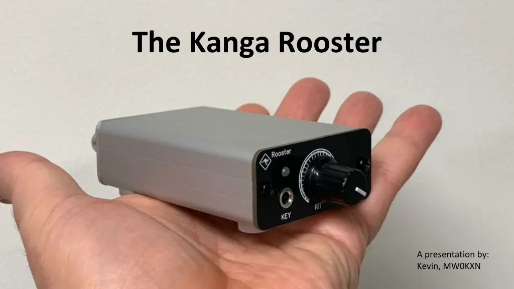
Rooster Specification An Easy build, fixed frequency, transceiver kit, for 40m or 30m Approx 20 parts to fit All SMD components are pre-installed No coils to wind and no alignment required. Approx. 2 Watts RF Output Low Pass Filter. 2nd harmonic suppression 46dB, 3rd harmonic 60dB Sidetone (A pleasant sinewave) Full Break-In with solid state switching Direct Conversion receiver Crystal RF bandpass filter Front panel RIT control Active Audio Filter Tiny form factor, attractive enclosure, printed front panel, strong aluminium case All for less than 40
Direct Conversion To understand what this means, and what it means for the Rooster, we need to do some revision. Let s start by looking at the block diagram of a Superheterodyne receiver.
Superheterodyne Receiver Block Diagram Two oscillators Intermediate Frequency stage Good image rejection Potential for narrow IF filters Rooster Receiver Block Diagram Simple circuit design No IF stage No Image rejection Very clean audio chain Susceptible to mains hum
The Rooster Direct Conversion Receiver Block Diagram NE5532 Low Noise Op Amp NE602 Double Balanced Mixer Antenna Audio Amp RF Mixer AF Filter RF Filter Sum, Diff, RF, VXO RF RF Audio, Image Audio, Image VXO Narrow, Crystal Band Pass Filter NE5532 (b) 700Hz Audio filter VXO RIT Signal Peaking Image Detection
Rooster Bandwidth In theory a direct conversion receiver without filtering has unlimited bandwidth. A typical adult has a hearing range from 20Hz to 12kHz. You would hear over half the CW segment of the band! Paul s clever use of a crystal ladder RF filter reduces the front-end bandwidth to a few kHz. The 700Hz audio filtering utilising the spare half of the dual operational amplifier improves the situation still further. The Rooster can t be considered to have narrow bandwidth filtering, but the combination of a crystal filter, a 700Hz audio filter, and RIT is surprisingly effective.
RX frequency offset for CW TX Freq RX Freq A CW signal has no audio, it is just a switched signal (OOK). If you select SSB on a receiver and tune towards a CW station, you will hear the tone drop in frequency. When you are perfectly tuned the station is zero beat . It is the difference in frequency between a TX station and the RX frequency that creates the tone or beat frequency. Selecting CW mode on a receiver shifts the frequency. The radio adds a frequency offset , creating an audible tone for stations around our TX frequency. 700Hz 7.030MHz 7.030 700 MHz
Direct Conversion Image Frequency TX Freq RX Freq Image Freq TX Freq RX Freq Image Freq 700Hz 700Hz 600Hz 800Hz 7.030 000MHz 7.030 000MHz 7.030 700MHz 7.031 400MHz 7.031 400MHz Mixing our incoming RF signal with a VXO signal creates 2 new signals: Sum (Approx twice our RX freq) Difference (Audio frequencies) Without an IF section differences signals are created for stations above and below our VXO frequency range. A station 700Hz above our offset RX will be indistinguishable from a station 700Hz below our offset RX frequency (our TX frequency). The unwanted signal is called the image frequency. Fortunately, when the RIT is adjusted the tone (freq) of two signals change in opposite directions.
The Crystal Oscillator A crystal oscillator is a mechanical oscillator, that resonates at a precise frequency, like the bell in a church tower! The Rooster requires the crystal oscillator to generate two frequencies. The resonant frequency of a crystal oscillator can be pulled a small amount by adding capacitance or inductance. The effect is not linear, the further that you pull the crystals frequency, the more it resists change. The Rooster VXO circuit is very clever, and provides: TX frequency adjustment, RX offset, and RIT If you choose to adjust the TX frequency far from Paul s recommendation, make sure that your RIT still covers your TX frequency.
CW Filters Our Rooster filtering is reasonably wide, we can hear stations near our frequency. Other stations will typically have more and narrower CW filters. Stations from 350Hz below our frequency to 850Hz above should be able to hear us if they are using their widest CW filter (Filter 1 above). Beyond this range they are unlikely to reply. Beware: The Rooster RIT will enable you to peak stations operating outside this range.
A shout out for QRP When there is no propagation there is no propagation. Extra power does not create propagation. When propagation is good you don t need lots of power. When propagation is marginal or you re trying to bust a pile up, extra power can enable you to shout louder than the crowd. 2 Watts is 17dB down on a 100w signal, nearly 3 S points. The Rooster operates on the QRP Centre of activity. People will be looking for your weak signals.
My Roosters TX frequency set to the maximum Maximise useful RIT range RIT knob vertical for stations on my frequency Additional labelling: TX frequency RIT frequency range and direction Differentiation of stations on image frequency RIT marker for lowest frequency likely to hear my calls